
Related Manuals for Macurco DVP-120B


Summary of Contents for Macurco DVP-120B
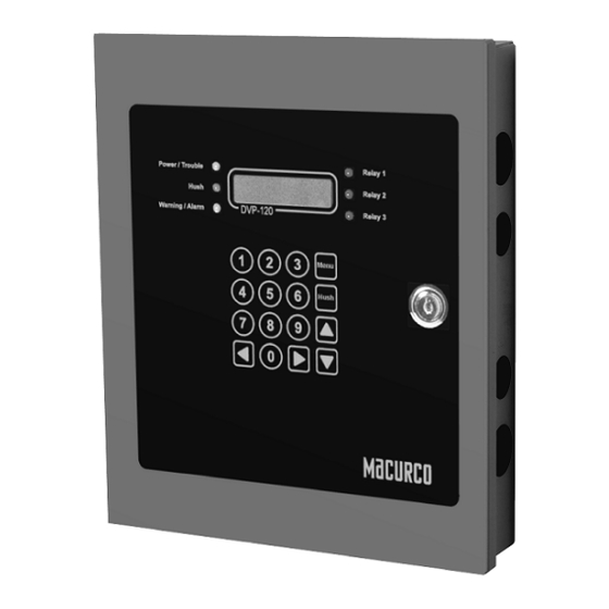
- Page 1 Macurco DVP-120B Detection and Ventilation Control Panel User Instructions IMPORTANT: Keep these User Instructions for reference.
-
Page 2: Table Of Contents
Binary Input - Over Range ........................41 5.1.5 Binary Input – Trouble ..........................41 5.1.6 Binary Input- DVP Com Error ........................41 Macurco Network Parameter Utility (NPU) ......................... 41 BACnet Connection ................................43 5.3.1 Serial RS-485 to USB Wiring ........................43 5.3.2... - Page 3 See section 4.3.8 Configure Signals Submenu for more detail ..............58 Appendix B – DVP-120 Setup Record ............................59 Appendix C – DVP-120B Setup Record ............................ 60 Macurco Gas Detection products limited warranty ........................62 Technical Support Contact Information ............................. 62...
-
Page 4: General Safety Information
For proper use, see supervisor or User Instructions, or call Macurco Technical Service at 1-844-325-3050. -
Page 5: Use Instructions And Limitations
The MRS-485 accepts the 4-20mA output and is powered from the same connection as the detector. The MRS-485 mounts to a Macurco 6-Series detector installed on a 4” x 4” electrical box electrical box supplied by the contractor. -
Page 6: Features
Modular input and output connectors • One RS-485 digital input channels - 87 addressable sensors RS-485 digital output channel for BACnet • Compatible with all Macurco 6-Series gas detectors and MRS-485 adapter • Twelve analogs (current loop) input channels •... -
Page 7: Installation And Operating Instructions
3050. This DVP-120 system should be used with Macurco™ transducers and each unit will measure the level of the target gas (i.e. CO, NO2, EX, etc.) and provide this information to the DVP-120 over a 4-20mA current loop. The transducers operate on low voltage (24VDC). All power and signal connections for the transducers are provided from the DVP-120 control panel, via unshielded four conductor cable. -
Page 8: General Wiring Information
(COM) and shield ground (SHD) connections. Use at least 3-conductor wire with one twisted pair providing a pair for signal (A & B) and common (COM) connections. The Macurco MRS-485 Modbus output is connected via a four-terminal screw type connector. -
Page 9: Main Power Connection
3.3 Main Power Connection The main power cable should be routed into the bottom left conduit entry. Macurco recommends a minimum wire size of AWG18 and the wire insulator must be rated for 140°F (60°C) service. The modular connector will accept wire from 12 to 24 AWG. The safety ground wire should be secured to the ground stud at the bottom left of the cabinet with the lock washer and nut supplied. - Page 10 Figure 3-4 DVP-120 Internal View and DVP-120B with DVP-485 Modbus Adapter Figure 3-5 Sensor Interface Connector – Channels 5 and 6 Each 8-terminal sensor modular connector may be disconnected from the PCB connector to ease wire installation. The terminals will accept wire from 16 to 28 AWG.
-
Page 11: Dvp-120B
MRS-485. The power connections to the remotely mounted detectors should be size AWG18 (minimum) for short runs. Since Macurco detectors are rated for operation between 12 and 24 VDC or VAC, the voltage drop between the power supply and the... - Page 12 from 16 to 28 AWG. To install a wire, strip back approximately 0.25 in. (6 mm) of insulation and insert the bare wire into the terminal. Tighten the screw clamp and ensure that the wire cannot be easily pulled from the connector. 3.4.2.5 Power Supply Selection of a UL recognized NEC Class 2 power supply which can power 12 MRS-485 connected to 6-Series detectors.
-
Page 13: Interfacing Macurco Sensors
The polarity of the current loop connections is marked on the printed circuit board of the sensor. 3.5.2 DVP-120B The Macurco MRS-485 Adapter converts the Macurco 6-Series 4-20mA analog output to a digital output for use with the DVP-120B and other addressable network systems... - Page 14 Connection The Macurco MRS-485 output is connected via a four-terminal screw type connector. The MRS-485 adapter is wired in the standard 2W- Modbus circuit definition with selectable built-in terminating resistors at the ends of the RS-485 bus. The power for the MRS-485 adapter is connected via a two-terminal screw type connector, 12 to 24 VAC or 12 to 24 VDC and no polarity.
- Page 15 3.5.2.3 Determining EOL Use At the baud rate of 19200 (default baud rate for Macurco MRS-485 and DVP-485) and with cables less than 1,000 ft. in length, termination resistors are not recommended. At the baud rate of 19200 and with cables longer than 1,000 ft., termination resistors are recommended.
- Page 16 Figure 3-12 At 19200 baud rate (default), 1000 ft or less and using RS-485 or Cat-5 type cable Figure 3-13 At 19200 baud rate (default), more than 1000 ft and using RS-485 type cable...
- Page 17 3.5.2.5 DIP Switches and Addressing Each MRS-485 (and the partner gas detector) must be configured to a unique address. If there are 10 detectors on the serial line, then 10 unique addresses must be used, one for each detector. To set the address, use the eight DIP switch positions. For each unit choose the value from 13 to 99 (see chart) and set the eight switches to match the address.
-
Page 18: Operations
4 Operations 4.1 Initial Operating Mode When power is first applied to the DVP-120, a few simple self-tests will be performed, and the system will cycle through all status lights, and display the system model and firmware version number (Figure 4-1). The system will then proceed to normal mode if the operating parameters have been entered. -
Page 19: User Interface
o Green (steady) – Relay 2 is on • RELAY 3 o Off – Relay 3 is not on o Green (steady) – Relay 3 is on The overall system status is visible at a distance via the status lights as described above. More detailed system information is displayed on the LCD, which can show the status of each relay and sensor. -
Page 20: Normal Status Display
4.1.6 Normal Status Display M O N 1 0 : 2 3 O F F S 0 1 P P M Figure 4-4 Normal System Display The display shows the day of the week and the time of day, in 24-hour format. It also shows the status of one of the relays, R1 in this example, and the type and indicated the gas concentration of one of the configured sensors, S01 is a CO sensor indicating 5ppm in this example. -
Page 21: Warning Status Display
When the HUSH key is pressed, the internal buzzer will be silenced for five (5) minutes. If the horn or strobe turn on delays have not finished then they will also be silenced. If the delays have finished the HUSH key must be held for three (3) seconds in order to silence the horn and strobe. -
Page 22: Ventilation Control
T r o u b l e S e n s o r Figure 4-10 Trouble display The display will cycle through all trouble indications, at five seconds per display. Pressing any key (except HUSH) will advance the display to the next trouble indicator. If an external horn and/or strobe are connected and configured to signal a trouble condition, they will also sound when a trouble condition occurs, after a delay, if that configuration option is selected. -
Page 23: Setting The System Configuration
Z O N E S I L E N C E D F O R M I N U T E S Figure 4-13 Zone Signal Silenced message 4.3 Setting the System Configuration The configuration menus can be entered from normal mode by pressing the MENU key. While in configuration mode, the user can review all configuration parameters to check the current operating conditions. -
Page 24: Configure System Submenu
Note that changes to the time and day of week are not considered configuration items; they are saved as soon as they are entered. NOTE: For DVP-120B, if baud rate for the panel is changed then “Reading Retries” Modbus parameter must be updated as per the following table. - Page 25 T i m e : 1 6 : 5 5 D a y : T u e s d a y Figure 4-19 Enter Minutes In this example, the hour (16) has been accepted and the panel is waiting for the minute to be entered. If no digits are entered within 5 seconds, the entry will be finished without changing the minute;...
- Page 26 DVP-120 will remain in normal mode. When new registration information is detected by the DVP-120, for example, if a different gas type of Macurco sensor was installed, the following message is displayed: “Configuration Changed Any key to save” is displayed.
- Page 27 Custom Sensor Implementation Custom sensor types or “wildcards” can be configured with the DVP-120. There are 8 Macurco sensor types and 21 custom sensor types available. Though the Macurco sensor data cannot be changed, custom sensor parameters can be configured to define the sensor type:...
- Page 28 Type: 01 Res.: 1 ppm Figure 4-23.8 Resolution “Res.” Defines the resolution used to display the reading, alarm, warning, range, falling level and rising level. It can have values between 1 and 500 when “Dec.” is 0, 50.0 when “Dec.” is 1 and 5.00 when “Dec.” is 2. Type: 01 Range: 200 ppm...
-
Page 29: Configure Sensors Submenu
Use only for monitoring the gases which the sensors and equipment are designed to monitor. Failure to do so may result in exposures to gases not detectable and result in serious injury or death. For proper use, see supervisor or User Instructions, or call Macurco Technical Service at 1-844-325-3050. - Page 30 Figure 4-28 Sensor Alarm Level This display example shows that the sensor on channel 01 has been configured as a Carbon Monoxide Sensor. The valid entries for Macurco type sensors are Carbon Monoxide (CO), Nitrogen Dioxide (NO ), Combustible Gas (EX), Ammonia (NH...
-
Page 31: Configure Relays, Horn & Strobe Submenu
4.3.3.5 Range S e n s o r R a n g e : 2 0 0 p p m Figure 4-29 Sensor Range The range for each sensor is the gas concentration that corresponds to the 20-mA signal level. The default range values for the sensors are: Carbon Nitrogen... -
Page 32: Configure Horn Submenu
Fail Safe operation can be implemented by configuring a relay to operate Normally On, and wiring the circuit using the NC (normally closed) contact. In this way, if the control panel loses power the relay will turn on the controlled device if it still has power. 4.3.4.3 Relay Turn on Delay R e l a y... -
Page 33: Configure Strobe Submenu
The default minimum on time is zero and the maximum allowed value is fifteen minutes. 4.3.6 Configure Strobe Submenu The configuration parameters for the strobe are the same as those for relays. A strobe would not normally require a minimum on time but this parameter allows a more versatile configuration. - Page 34 Zone 1 controls Relay 1 • Zone 2 controls Relay 2 • Zone 3 controls Relay 3 • 4.3.7.1 Zone Controls Z o n e C o n t r o l s Figure 4-40 Zone Controls This display example shows that Zone 1 is configured to control all of the relays plus the horn and the strobe. Each of the relays, the horn, and the strobe can be removed from (or added to) the zones control by pressing the indicated digit key.
- Page 35 • 9 Carbon Dioxide (CO The default Types are: Group 1 in each zone Type 1 CO, Voting mode, Quorum = 1 Group 2 in each zone Type 2 NO , Voting mode, Quorum = 1 Group 3 in each zone Type 3 EX, Voting mode, Quorum = 1 Group 4 in each zone Type 4 NH...
- Page 36 Sensors are included or removed from the group by entering the two-digit channel number. After a sensor is added or removed, the list will be re-sorted so it does not matter in which order the sensors are added or removed. The default is to include all sensors of the specified type.
-
Page 37: Configure Signals Submenu
When multiple sensors are being monitored by a group, the output decision can be based on either voting, as shown here, or the average of all sensors in the group. Valid modes are: Average • Voting (default) • When the configuration is Average, the gas concentrations from all sensors in the group are averaged and if the average is greater than or equal to the rising trip point the zone outputs(s) are activated. - Page 38 Double tap Two beeps at five-second intervals • Triple tap Three short beeps at ten-second intervals • Buzzer will not sound • 4.3.8.3 Alarm Horn Signal A l a r m S i g n a l s H o r n : 2 I n t e r m i t .
- Page 39 Double tap Two beeps at five-second intervals • Triple tap Three short beeps at ten-second intervals • Buzzer will not sound (default) • 4.3.8.7 Warning Horn Signal W a r n i n g S i g n a l s H o r n : 5 O F F Figure 4-57 Strobe Warning Signal...
- Page 40 Double tap Two beeps at five-second intervals • Triple tap Three short beeps at ten-second intervals (default) • Buzzer will not sound • 4.3.8.11 Trouble Horn Signal T r o u b l e S i g n a l s H o r n : 5 O F F Figure 4-61 Horn Trouble Signal...
-
Page 41: Bacnet
Analog Input - Sensor ID The value in the BACnet object refers to the Sensor ID/Type of Macurco Gas detector and value will have 6 trailing zeros e.g. for CM-6 value will be 1.000000. Values of 1 to 8 are only valid values. - Page 42 This value must be greater than or equal to device address. Set this field to 127 if the highest address on the network is unknown. Reload button - Will load the current settings for DVP-120B. To change the settings (on BACnet end) in DVP-120B, change the parameter in DVP-120B and hit Submit.
-
Page 43: Bacnet Connection
Serial RS-485 to USB Wiring Most converter cables are going to come with more wires than what is needed by the Macurco DVP-120B BACnet output. The extra wires do not have a termination point and should be secured and protected from shorting using tape or heat shrink. -
Page 44: Serial Rs-485 To Ethernet (Tcp/Ip)
Follow the wiring diagram for your specific Serial RS-485 to Ethernet converter. 5.4 BACnet software There are a number of software applications available to read the BACnet output of the Macurco DVP-120B Control panel. For more information on these please contact Macurco Support at 1-844-325-3050 or... -
Page 45: Troubleshooting
Macurco sensors may be tested by depressing the TEST button on the sensor printed circuit board, or (depending on the type of sensor), the button on the interior front panel of the unit. Macurco sensors will step the output current level from 4 mA to 20 mA over the course of the warm-up period, allowing the technician to determine where the trouble condition exists. -
Page 46: Internal Controller Board Trouble
If the sensor status display and investigative efforts reveal no problems with the input channel current loops and channel configuration, the most likely trouble condition is an internal problem detected by the DVP-120 controller. In this case, contact the Macurco Technical Support at 1-844-325-3050 for advice and help. -
Page 47: The Keypad Does Not Respond After Silencing An Alarm, Warning Or Trouble
6.6 The Keypad does not respond after silencing an Alarm, Warning or Trouble. LCD continues to show the alarm, warning or trouble message. It is possible that the horn or strobe have been configured to respond in alarm, warning or trouble conditions, even though there is no horn or strobe connected (or perhaps they are used for some purpose that is not audible or visible). - Page 48 RED/OFF Alternating every 200 milliseconds indicates that saving new settings failed. GREEN/OFF Alternating every 200 milliseconds indicates that saving new settings passed. RED/OFF Alternating every 500 milliseconds indicates that selected MODBUS address is not an accepted value.
-
Page 49: Testing And Maintenance
Table 7-1 Keypad keys for Testing Functionality 5. If all test is complete, turn off the DVP-120 or DVP-120B. Move the jumper back to bottom two pins of EXT connector for DVP- 120 and right two pins of J10 for DVP-120B. -
Page 50: Appendix A - Quick Setup
8 Appendix A – Quick Setup IMPORTANT: To properly and effectively program the system you must configure the Sensors, Relays, Zones, and Signals. If the user has not entered any parameters, the system WILL NOT be monitoring the sensors or controlling the ventilation system. The relays will be in the not actuated state and the horn and strobe outputs will be off. - Page 51 (see the User Instructions for each sensor type for location and coverage details). Extra sensors may be needed near areas where people work, such as toll booths. Macurco provides only the control panels and sensors. Fans, relays, and other devices are provided by the contractor.
-
Page 52: Configure System Submenu
Setting the System Configuration The configuration menus can be entered from normal mode by pressing the MENU key. While in configuration mode, the user can review all configuration parameters to check the current operating conditions. S E N S O R S F O U N D R E L A Y S F O U N D... - Page 53 4. Change Password T i m e : 2 2 : 5 5 D a y : T u e s d a y Figure A-5 Set Time of Day This display example shows that the time is 22:55 (10:55 PM). The underlined numerals indicate that the numeric keys can be used to set the current time of day.
-
Page 54: Configure Sensors Submenu
E n t e r P a s s w o r d _ _ _ _ Figure A-9 Enter Password If the password is not entered correctly the panel will display as follows: W r o n g P a s s w o r d Figure A-11 Wrong Password Prompt Once the current password has been entered, the panel will prompt for the configuration parameter being changed. -
Page 55: Configure Relays, Horn & Strobe Submenu
↑ Alarm Level - set level if needed, 0 = disable S e n s o r A l a r m : 2 0 0 p p m Figure A-14 Sensor Alarm Level ↑ Warning Level - set level if needed S e n s o r W a r n i n G : _ 5 0 p p m... -
Page 56: Configure Zones Submenu
Default - Minimum Runtime - 1 Minute R e l a y M i n . O n ( m m : s s ) 0 1 : 0 0 Figure A-20 Minimum on Time → Relay 2 - repeat for all relays, horn, and strobe 8.4 Configure Zones Submenu 8.4.1 See section... - Page 57 ↑ Rising (activation) Trip point G r o u p N O 2 R i s i n g : 2 . 5 p p m Figure A-24 Rising Trip Point Entry The default rising trip points are: Carbon Nitrogen Combustible Hydrogen Carbon...
-
Page 58: Configure Signals Submenu
If a group has an equal number of sensors with gas readings greater than or equal the rising trip point and sensors with • readings less than or equal to the falling trip point, activating the output(s) is given priority. It is up to the installer to ensure that the Quorum entry is appropriate for the configuration. -
Page 59: Appendix B - Dvp-120 Setup Record
9 Appendix B – DVP-120 Setup Record Record network parameters and keep in a safe place to assist with installation and future troubleshooting will be simplified. Date of Install: ______________________________________ Serial Number: _____________________________________ Location of Install: __________________________________ Installed by: ________________________________________ Detectors / Sensors Under Detector type record gas type (e.g. -
Page 60: Appendix C - Dvp-120B Setup Record
10 Appendix C – DVP-120B Setup Record Record network parameters and keep in a safe place to assist with installation and future troubleshooting will be simplified. Date of Install: ______________________________________ Serial Number: _____________________________________ Location of Install: ___________________________________ Installed by: ________________________________________ Detectors / Sensors Under Detector type record gas type (e.g. - Page 61 11 Appendix D – DVP-120 Quick Start Guide...
-
Page 62: Macurco Gas Detection Products Limited Warranty
12 Macurco Gas Detection products limited warranty Macurco warrants the DVP-120B gas detector will be free from defective materials and workmanship for a period of two (2) years from the date of manufacture (indicated on inside cover of the DVP-120), provided it is maintained and used in accordance with Macurco instructions and/or recommendations.
Need help?
Do you have a question about the DVP-120B and is the answer not in the manual?
Questions and answers