Table of Contents
Advertisement
Quick Links
SYSTXBBECC01-B, SYSTXBBWEC01-B,
SYSTXBBECF01-B, SYSTXBBWEF01-B
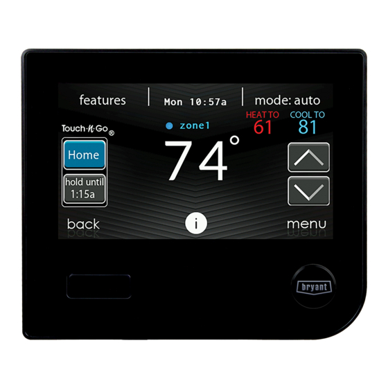
Evolution® Connex™ Control
NOTE: Read the entire instruction manual before starting the installation.
NOTE: Please refer to the literature provided with the connected HVAC equipment for more
details on system operations with specific pieces of equipment.
The features and functions outlined in the Installation Instructions reflect Version 1.3 or later
software. Occupancy sensing compatibility is only available with Series B Evolution Connex
Control. See the Evolution Connex product page on the HVACPartners.com website or the
Downloads section of the
release and literature.
US Patents: Carrier U.S. Pat No. 7,243,004, U.S. Pat No. 7,775,452, pointSET™ U.S. Pat No.
7,415,102
Installation Instructions
A180277
www.MyEvolutionconnex.Bryant.com
A180218B
website for the latest software
Advertisement
Table of Contents

Related Manuals for Bryant Evolution Connex Control


Summary of Contents for Bryant Evolution Connex Control
- Page 1 Occupancy sensing compatibility is only available with Series B Evolution Connex Control. See the Evolution Connex product page on the HVACPartners.com website or the Downloads section of the www.MyEvolutionconnex.Bryant.com website for the latest software release and literature. US Patents: Carrier U.S. Pat No. 7,243,004, U.S. Pat No. 7,775,452, pointSET™ U.S. Pat No.
-
Page 2: Table Of Contents
Table of Contents Page 1. Safety Considerations ..............6 2. - Page 3 6.2. Installation..............21 6.3.
- Page 4 6.3.8.2. Zone Offsets ............37 6.3.8.3.
- Page 5 8. Wiring Diagrams ..............56 9.
-
Page 6: Safety Considerations
1. Safety Considerations Improper installation, adjustment, alteration, service, maintenance, or use can cause explosion, fire, electrical shock, or other conditions which may cause death, personal injury or property damage. Consult a qualified installer, service agency or your distributor or branch for information or assistance. -
Page 7: Quick Start
When using a Bryant HRV or ERV with a zoned system, the Evolution System Zone board allows connection of a Bryant HRV or ERV without the need for separate wall control or NIM. All system components are controlled through the wall mounted Evolution Connex Control, which replaces the conventional thermostat and provides the homeowner with a single wall control for all features of the system. -
Page 8: Set Dealer Information
4. Installation 4.1. Overview This instruction covers installation of the Evolution Connex Control only. Physical installation instructions for the indoor and outdoor equipment, and accessories are provided with each unit. Setup, commissioning, operation, and troubleshooting of the Evolution System are covered in this installation instruction at a high level. -
Page 9: Check Equipment
All wiring must comply with national, state, and local codes. 4.3.1. Wall Control The Evolution Connex Control is the command center for the Evolution System. It should be located where it is easily accessible and visible to the adult homeowner or end user. For accurate... -
Page 10: Wired Remote Room Sensors
4.3.2. Wired Remote Room Sensors A Remote Room Sensor can be used with the Evolution Connex Control to take the place of the control’s internal temperature sensor. This allows the Evolution Connex Control to be mounted in areas with less than optimal airflow (such as near an exterior door, window or in a closet). -
Page 11: Wiring Considerations
4.4. Wiring Considerations Ordinary thermostat wire is recommended. See Shielded Wire and Communication Bus Configuration Section for notes on shielded wire. Continuous wire lengths over 25 ft. should use 18 AWG wiring. NOTE: ABCD bus wiring only requires a four-wire connection; however, it is good practice to run thermostat cable having more than four wires in the event of a damaged or broken wire during installation. -
Page 12: Damper Control Module (Zoning Systems Only)
The shield wire should be connected to the C terminal, or ground, AT THE INDOOR UNIT, ONLY. The shield wire should NOT be connected to any terminal at the Evolution Connex Control. Connecting the shield to ground at both ends can cause current loops in the shield, reducing shield effectiveness. -
Page 13: Decorative Trim Plate
Align the trim plate around the backplate, and snap on the system control. NOTE: Once the Evolution Connex Control is secured to wall with the backplate assembly (snapped together), care must be taken not to bend or break the interlocking tabs when removing. -
Page 14: Humidifier Connections
• Attach Evolution Connex Control to the mounting plastic by lining up the plastic guides on the back of the control with the opening on the mounting plastic and push on. -
Page 15: Commissioning
Instructions for more details, as provided. 5.1. Searching for Indoor Unit The Evolution Connex Control will light up and display the Brant logo and then begin the commissioning process by displaying “Searching for indoor unit”. NOTE: If the Evolution System-compatible indoor equipment (package unit indoor section, gas furnace or fan coil) cannot be found, the control will display “Indoor unit not found”. -
Page 16: Indoor Evaporator Selection
Refrigerant Charging Greenspeed® Intelligence, 18VSt, 19VSt Systems Section. Select “other” for non-Bryant evaporators. 5.4. Electric Heater Selection If the indoor equipment is a fan coil, the control will display “Searching for heater” until one is found. -
Page 17: Hydronic Heat Application
SYSTXCCRCT01 and SYSTXCCRWF01. The SAM is used for home automation purposes and is NOT used to connect the system control to the Internet. The Evolution Connex Control must have at least Version 8 software or newer to be compatible with the SAM. -
Page 18: Searching For Zones (If Applicable)
A13117 5.6. Searching for Zones (If Applicable) “Zoning - Searching” will appear on the screen to determine if any zones are present. The screen will show Zone 1, Zone 2, etc. and indicate all zones having either a Remote Room Sensor, or smart sensors associated with them. -
Page 19: Ultraviolet Lights Installation
5.9. Ultraviolet Lights Installation Next, the installer will be prompted to select whether ultraviolet lights are installed in the system. Select YES or NO, then touch NEXT. 5.10. Equipment Summary The equipment summary screen will appear after accessories have been selected. This screen will give a summary of all equipment automatically found or manually selected. -
Page 20: Duct Assessment (Zoned Systems Only)
If the Evolution Connex Control detects an error (damper not moving or damper wired backwards), it will perform the duct assessment again. If it still detects a damper problem, it will default the measurements into equal sizes, with 10% leakage, and display the zone number for the suspected zone damper. -
Page 21: Equipment Summary
service. To return to the previous screen, touch BACK. To exit the Service menus, touch DONE. NOTE: See the Owner’s Manual for information regarding software upgrades. NOTE: The user “selection of temperature units” affects the user screens only. The service screens use degree F only. -
Page 22: Set Up
Touch Airflow Verification Test to perform a duct assessment. This can be done if duct modifications have been made since installation of the Evolution Connex Control. Duct assessment can be performed without performing a full system install. NOTE: This feature is only available with specific ICP communicating indoor units. See the Ion System Control Product Data for compatible units and more information. -
Page 23: Thermostat
6.3.1. Thermostat First touch SETUP, then touch THERMOSTAT to set up the parameters for the Evolution Connex Control. 6.3.1.1. Auto Mode Set Up Once the auto changeover option has been selected, touch SAVE. • Enable or Disable: Choose to enable or disable auto changeover mode. Default = Enable •... -
Page 24: Offsets
6.3.1.3. Offsets This option allows calibration (or deliberate miscalibration) of the temperature and humidity sensors. These offsets are added to the actual temperature/humidity values. See also Zone Offsets Section. When the correct offsets are made, touch SAVE. If the system is non-zoned, the indoor temperature offset is found on this screen. -
Page 25: Scheduling On/Off
6.3.1.5. Scheduling On/Off This option lets the installer allow comfort schedule programming features. After the selection is made, touch SAVE. • Scheduling: On or Off. Default = On 6.3.1.6. Smart Recovery On/Off NOTE: ”Smart Recovery” refers to transitions between and among the Home, Sleep and Wake modes. -
Page 26: Altitude
mode is increased to reduce duct and register sweating. Also the airflow increases minimum airflow during normal cooling operation to help reduce duct sweating. After the selections are made, touch SAVE. • Cooling Airflow: Quiet, Comfort, EFF325 (or EFF1), EFF350 (or EFF2), or Max. Default = Comfort •... -
Page 27: Fan Coil G-Terminal Alert
– The shutdown function may not be immediate. Blower off delays, etc., will still be used. The shutdown is not intended for commercial applications. If immediate shutdown is required, provision must be made to remove power to indoor unit. A13229 6.3.2.5. -
Page 28: Furnace
6.3.3. Furnace First touch SETUP, then touch FURNACE to set up the parameters for the furnace unit. A14225A_2 6.3.3.1. Furnace Airflow Selects the airflow of the furnace when heating. EFFICIENCY is the airflow used to meet specified ratings, COMFORT is a decreased airflow used to increase the output air temperature and provide increased comfort. -
Page 29: Furnace Staging
The dehumidify airflow, when set to NORMAL, the airflow is allowed to adjust to a minimum to satisfy the dehumidification call. When set to HIGH, the minimum airflow during the dehumidify mode is increased to reduce duct and register sweating. Also the airflow increases minimum airflow during normal cooling operation to help reduce duct sweating. -
Page 30: Furnace Dehumidifier Drain
• Altitude: 0000 – 2000, US 2001 – 3000, CN 2100 – 4500, US 3001 – 4000, US 4001 – 5000, US 5001 6000, US 6001 – 7000, US 7001 – 8000, US 8001 – 9000, and US > 9000. Default = US 2001-3000 •... -
Page 31: Furnace G Terminal Alert Label
Shutdown: This setup option selects the change of state required for shutdown. Select Normally Open or Normally Closed, and then save your selection. 6.3.3.10. Furnace G Terminal Alert Label Once the G Terminal Alert label has been entered, it is shown both on the main screen and in the notification email when the alert becomes active. -
Page 32: Cooling Lockout
• High Cool: Temperature above which only the high stage of cooling will be energized. • Only Low Cool: The system will only run in low stage cooling. High Heat Latch A13228 • System in Control: The system will decide which stage should be running to satisfy the heating demand. -
Page 33: Quiet Shift
6.3.4.5. Quiet Shift This option turns on Quiet Shift function in 1-stage or 2-stage communicating heat pumps. After the selection is made, touch SAVE. NOTE: This option is not available with variable speed heat pumps nor geothermal units. • Quiet Shift: On or Off. Default = Off 6.3.4.6. -
Page 34: Stages / Latch For 18Vs
A12149 • HP Lockout: Adjustable from -20 to 55°F (-28 to 13°C) or None. Default = None • Furnace, Electric Heat or Hydronic Lockout: Adjustable from 15 to 55°F (-9 to 13°C) or None. Default = None • Defrost with Furnace, Electric Heat or Hydronic: Yes or No. Default = Yes –... -
Page 35: Freeze Limits
A160188b 6.3.7.1. Freeze Limits This setting controls the temperature level to which the loop liquid can drop before the Geo HP unit will stop operating. See the Geo HP Installation Instructions for more details. Typically, 26°F is chosen for open-loop systems using untreated water; and 15°F is chosen for closed-loop systems using glycol or other anti-freeze solutions. -
Page 36: Brownout Override
A150180 6.3.7.3. Brownout Override This option controls the low voltage brownout override function in the Geo HP unit. After the selection is made, touch SAVE. • Brownout Override: Active or Inactive. Default = Inactive A150181 6.3.7.4. Geothermal HP Energy Tracking Energy tracking for geothermal heat pumps requires the installation of an Entering Water Temperature (EWT) sensor. -
Page 37: Disable Zoning
A12191 6.3.8.1. Disable Zoning This option allows the installer to enable or disable zoning. After the selection is made, touch SAVE. • Disable Zoning: Yes or No. Default = No 6.3.8.2. Zone Offsets This option allows actual temperature offset for each zone, allowing calibration (or deliberate miscalibration) of each sensor. -
Page 38: Accessories
equipment, since duct system changes may occur at any time, such as opened or closed registers. This option allows the installer to select the time in which the duct assessment will be performed. After the selection is made, touch SAVE. •... -
Page 39: Ventilator
6.3.9.4. Ventilator When a ventilator is installed, the installer has the option of selecting the time interval for cleaning the ventilator. After the selections are made, touch SAVE. • Clean Interval: Selectable from 60, 90, 120, 150 or 180 days. Default = 90 days NOTE: This option may NOT be available with the ERVXXNVA ventilator due to its simplified control design. -
Page 40: Check Out
equipment, since duct system changes may occur at any time, such as opened or closed registers. This option allows the installer to select the airflow for the fan coil when paired with a hydronic coil. After the selections are made, touch SAVE. A12194 •... -
Page 41: Electric Heat
6.4.1. Electric Heat If you have a fan coil with electric heaters, this menu item will allow the heaters to be exercised. With self-identifying electric heaters, three stages of electric heat are available to be exercised in any combination. Non-identifying heaters will only provide one stage of heat; or perhaps may have fixed-timed staging. -
Page 42: Heat Pump Heating
6.4.5. Heat Pump Heating The heat pump heating mode can be exercised with this menu option. With a 2-stage heat pump, a Low Heat and a High Heat Run Time are independently selectable to exercise. For variable speed heat pumps, you can select the speed at which the heat pump will exercise. For VS heat pumps, you can select the stage at which the heat pump will exercise. -
Page 43: Ventilator
6.4.8. Ventilator The ventilator can be exercised through all of its operating speeds with this menu option. To end the ventilator checkout, touch STOP. • Humidifier Check: High, Low or Off NOTE: This option may NOT be available with the ERVXXNVA ventilator due to its simplified control design. -
Page 44: Zone Duct Assessment
6.4.9.3. Zone Duct Assessment This screen shows the results from the previous duct assessment. The duct assessment is performed at initial start-up and at 1 P.M. or the installer selected time each day. If another duct assessment is desired, the service technician should perform a re-install of the system. NOTE: A Duct Assessment will automatically occur every 24 hours at selected time to check system static and calibrate dampers. -
Page 45: Furnace Status
A12197 6.5.3. Furnace Status The furnace status screen displays relevant information about the furnace operation. To return to the previous screen, touch BACK. To exit the Service menus, touch DONE. A12198 6.5.4. AC Status The AC status screen displays relevant information about the AC operation. To return to the previous screen, touch BACK. -
Page 46: Geothermal Hp Status
A12200 6.5.6. Geothermal HP Status The Geo HP status screen displays relevant information about the Geo HP operation. To return to the previous screen, touch BACK. To exit the Service menu, touch DONE. NOTE: Screen data will vary based on unit installed. A160192 6.5.7. -
Page 47: Run/Fault History
A12151 6.5.9. Run/Fault History This information is stored in the equipment circuit boards (if communicating) and displayed on the control. The indoor unit and outdoor unit (if communicating) have the following histories. To return to the previous screen, touch BACK. To exit the Service menus, touch DONE. •... -
Page 48: Energy Tracking
The contact number can be changed under the dealer system menu. To return to the previous screen, touch BACK. To exit, touch DONE. 6.5.12. Energy Tracking NOTE: Energy Tracking is only available for applicable equipment. See The Product Data for the equipment in question to see if Energy Tracking is available for that device. -
Page 49: Pump Down
Next, the installer will enter the SERVICE VALVE SUBCOOL screen. This screen will show the current liquid line subcool target (in °F). To begin the charging, touch START. If the outdoor temperatures are not in the required range, Service Valve Subcool may not be available. For HTG CHECK CHARGE, the option Service Valve Subcool is unavailable. -
Page 50: Evacuation
SYSTXBBECC01-B > Documents > Marketing > Miscellaneous > Evolution Connex Control Dealer Logo Application - Instructions. Touch DEALER LOGO to upload the dealer logo and contact information from a micro SD card connected to the Evolution Connex Control. The “Dealer Logo Application” PC/MAC Desktop application... -
Page 51: Utility Event Setup
Once the dealer logo and contact information have been properly loaded onto the micro SD card, insert the micro SD card into the bottom edge of the Evolution Connex Control. The control will prompt you whether or not to upload the dealer logo. Once complete, you will receive a confirmation that your upload was successful. -
Page 52: Setup And Status Information (Homeowner's Router)
The ability to remotely access and adjust the settings of the Evolution Connex Control with the MyEvolution web and mobile applications is dependent on the compatibility of the user’s computer/network or mobile device, the Evolution Connex Control, and/or the MyEvolution web server with, and the availability of, the user’s Internet service provider or mobile device... - Page 53 A13235 • On the next screen look for the SSID of the router. After being selected, it will be outlined in faint blue and indicated by a check mark. Then select NEXT. A150175 • The selected network will show. Choose an appropriate Wi-Fi network security mode. Usually auto-detect will correctly identify the type of security mode used.
- Page 54 This requires the MAC address and serial number of the Evolution Connex Control. To find the serial number and MAC address of the Evolution Connex Control, click on Menu, Down Arrow, Wireless and View MyEvolution Registration Info.
- Page 55 A13242B A180093...
- Page 56 8. Wiring Diagrams Variable-Speed Furnace/ Fan Coil Communicating AC, HP or GHP* User Interface Green - Data A Green Yellow - Data B Yellow White - COM White Red - 24VAC Optional Remote Room Sensor ABCD Humidifier Connections Connection Sensor (Optional) *NOTE: Some outdoor units do not require the “C ”...
- Page 57 Variable-Speed Furnace/Fan Coil User Interface Green - Data A Yellow - Data B ABCD White - COM Connection Red - 24VAC 1-Spd. Optional Remote Non-Communicating Room Sensor Humidifier Connection Y/Y2 Sensor A12354 Connection Diagram for Furnace or FE Fan Coil with 1-Stage Air Conditioning...
- Page 58 Variable-Speed Fan Coil User Interface Green - Data A Yellow - Data B ABCD White - COM Connection Red - 24VAC 1-Spd. Optional Remote Non-communicating Room Sensor Humidifier Connection Sensor A12355 Connection Diagram for FE Fan Coil with Non-communication 1-Stage Heat Pump...
- Page 59 Indoor Communicating Unit AC or HP Zone Control User Interface & Smart Sensor(s) Green Yellow A B C D White A B C D A B C D Humidifier Connection Damper Control module Sensor (Optional) A04018 Zoning Connection for Communicating Indoor Unit with 2-Stage Communicating Outdoor Unit NOTE: Some outdoor units do not require “C”...
- Page 60 Indoor Unit Zone Control User Interface & Smart Sensor(s) Green Yellow A B C D White 1-Stage AC A B C D A B C D Humidifier Connection Damper Y/Y2 Control module Sensor A04019 Zoning Connection Diagram for Furnace or FE Fan Coil with Non-Communicating 1-Stage Air Conditioning...
- Page 61 Variable-Speed Zone Control Fan Coil User Interface & Smart Sensor(s) Green Yellow A B C D White 1-Spd. HP A B C D A B C D Humidifier Connection Damper Control module Sensor A07149 Zoning Connection Diagram for FE Fan Coil with Non-communicating 1-Stage Heat Pump...
- Page 62 A160170 NIM Chart A160171 Wiring Diagram Single-Stage Non-Communicating Heat Pump...
- Page 63 A160172 Wiring Diagram Two-Stage Non-Communicating Heat Pump NIM...
- Page 64 FE Fan Coil or Variable Speed Furnace A07114 G Input Wiring for Blower Operation...
- Page 65 FE Fan Coil or Variable Speed Furnace A07115 G Input Wiring for System Shutdown 9. Statement Information This device complies with Part 15 of the FCC Rules. Operation is subject to the following two conditions: (1) This device may not cause harmful interference, and (2) This device must accept any interference received, including interference that may cause undesired operation.
- Page 66 interference to radio or television reception, which can be determined by turning the equipment off and on, the user is encouraged to try to correct the interference by one or more of the following measures: • Reorient or relocate the receiving antenna. •...
- Page 68 © 2020 Carrier. All rights reserved. A Carrier Company Catalog No: II-SYSTXBBECC-08 997-017060-28-R Edition Date: 09/20 Replaces: II-SYSTXBBECC-07 Manufacturer reserves the right to change, at any time, specifications and designs without notice and without obligations.
Need help?
Do you have a question about the Evolution Connex Control and is the answer not in the manual?
Questions and answers