Table of Contents
Advertisement
SYSTXBBUIZ01- -B
EVOLUTIONt CONTROL
HOLD
E
VOLUTION
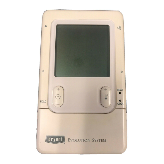
Fig. 1 - - Evolutiont Zone Control
Installation Instructions
HEAT
COOL
OFF
S
™
YSTEM
A04032
NOTE: Read the entire instruction manual before starting the
installation.
TABLE OF CONTENTS
. . . . . . . . . . . . . . . . . . . . . . . . . . . . . . . . . . .
. . . . . . . . . . . . . . . . . . . . . . . . . . . . . . . . . . . .
. . . . . . . . . . . . . . . . . . . . . . . . . . . . . . . .
. . . . . . . . . . . . . . . . . . . . . . . . . . . . . . . . . . . . .
. . . . . . . . . . . . . . . . . . . . . . . . . . . . . . . . . . . .
. . . . . . . . . . . . . . . . . . . . . . . . . . . . . . . . . . . . . .
. . . . . . . . . . . . . . . . . . . . . . . . . . . . . . .
. . . . . . . . . . . . . . . . . . . . . . . . . . . . . . . . . .
. . . . . . . . . . . . . . . . . . . . . . . . . . . . . .
SAFETY CONSIDERATIONS
Read and follow manufacturer instructions carefully. Follow all
local electrical codes during installation. All wiring must conform
to local and national electrical codes. Improper wiring or
installation may damage the Evolution Zone System. Recognize
safety information. This is the safety- -alert symbol
see this symbol on the equipment and in the instruction manual, be
alert to the potential for personal injury. Understand the signal
words DANGER, WARNING, and CAUTION.
These words are used with the safety- -alert symbol. DANGER
identifies the most serious hazards, which will result in severe
personal injury or death. WARNING signifies a hazard, which
could result in personal injury or death. CAUTION is used to
identify unsafe practices, which may result in minor personal
injury or product and property damage. NOTE is used to highlight
suggestions which will result in enhanced installation, reliability, or
operation.
PAGE
. . . . . . . . . . . . . . . . . . . . . . . . .
. . . . . . . . . .
. . . . . . . . . . .
. . . . . . . . . . . . . . . . . . . . . . . . .
. . . . . . . . . . . . . . . . . . . . . .
. . . . . . . . . . . . . . . . . . . . .
. . . . . . . . . . . . . . . . . .
. When you
1
2
2
2
5
6
8
9
9
9
9
13
14
16
18
19
Advertisement
Table of Contents

Subscribe to Our Youtube Channel
Related Manuals for Bryant EVOLUTION Zone Control SYSTXBBUIZ01-B


Summary of Contents for Bryant EVOLUTION Zone Control SYSTXBBUIZ01-B
-
Page 1: Table Of Contents
SYSTXBBUIZ01- -B EVOLUTIONt CONTROL Installation Instructions NOTE: Read the entire instruction manual before starting the installation. TABLE OF CONTENTS PAGE SAFETY CONSIDERATIONS ......INTRODUCTION . -
Page 2: Introduction
24 volt signals needed to control them. Also, the Evolution Damper Control Module (P/N SYSTXBB4ZC01) Evolution Zone Control Location allows connection of a Bryant HRV or ERV without the need for a The Evolution Zone Control User Interface is the command center separate wall control. - Page 3 Remote Sensor Averaging It may be mounted in either vertical or horizontal position. Remember that wiring access is likely the most important Typically, one Remote Room Sensor is used per zone, but multiple consideration. sensors may be used and averaged in some applications. Averaging requires a special series- -parallel wiring method with a specific CAUTION number of sensors.
- Page 4 Surface Mount Backplate to wall Interlocking Tabs (4) A03186 A03191 Fig. 4 - - Recessed Mount Backplate Fig. 8 - - Surface Mount Assembly A03188 Fig. 9 - - Large Decorative Backplate A03187 Fig. 5 - - Surface Mount Backplate A03192 Fig.
-
Page 5: Installing Evolution Zone Control
INSTALLING EVOLUTION ZONE NOTE: It is not mandatory that the above color code be used, but each ABCD connection in the system MUST be wired consistently. CONTROL A separate ABCD Connector comes inside packaging and should be used when connecting to furnace (or fan coil). Ensure connector WARNING is inserted properly into circuit board. -
Page 6: Initial Power- -Up
Bypass Humidifiers Indoor Communicating Unit AC or HP Zone Control A bypass humidifier should be wired directly to the furnace or fan User Interface & coil HUM and 24VAC COM terminals. The Evolution Zone Smart Sensor(s) Green Control will automatically energize the HUM output during a call Yellow A B C D for humidification. - Page 7 Once the indoor and outdoor equipment has been found, the If the equipment is a fan coil, packaged heat pump, or packaged Installer will be asked to select Accessories. Packaged Products AC and the electric heater is not self- -identifying, “ELECTRIC will be automatically identified and the Installer will be asked to HEATER NOT IDENTIFIED”...
-
Page 8: Quick Start
Zoning take about 1 1/2 minutes to complete. When completed, a screen will appear displaying the static pressure (in inches) across the “SEARCHING FOR ZONE EQUIPMENT” will appear on the equipment at the expected highest delivered airflow. If the static screen to identify the number of zones detected. -
Page 9: Install / Service Menus
12. To exit press BASIC button or close door. INSTALL/SERVICE 13. If changes are made, you will be asked to “SAVE EQUIPMENT SUMMARY CHANGES? YES/NO.” INSTALL SETUP Override Heating Schedule CHECKOUT SERVICE 1. Press the red HEAT button. Heating mode is confirmed when the red LED next to the red HEAT button is lit. - Page 10 This menu has several layers, allowing modification of equipment Last 10 System Events: settings. No settings will need to be made at equipment (i.e. DIP Yes/No to reset last 10 system events under Service Info switches on a furnace). All configuration settings made effective menu.
- Page 11 terminal shutdown event in Last 10 System Events. See EFFICIENCY - - fixed airflow used to achieve specified Fig. 29. ratings - - no dehumidification airflow reduction. This is nominally 350 CFM/ton, but will vary if a 2- -stage out- GEN (generator input) - - displays GENERATOR MAL- door unit is used.
- Page 12 60 minutes This option allows actual temperature offset for each zone, allowing calibration (or deliberate miscalibration) of each sensor. 90 minutes Humidifier interval is time only, not actual humidifier run time. 120 minutes (default) Airflow Limits: Auto- -Defrost interval optimized by outdoor control (de- fault for communicating HP) Since bypass damper is prohibited in this system, this setting is used to select the maximum allowable noise/airflow relationship...
-
Page 13: Checkout Menus
Setup - - Accessories This setup is available only if the equipment has a utility saver input (refer to equipment Installation Instructions.) This setup Filter Type: controls the response of the equipment when the utility saver input MEDIA (i.e. TrueSenset) is active. -
Page 14: Service Menus
The heat pump cooling mode (or AC cooling mode) can be the indoor unit will provide the maximum airflow for that zone (as exercised with this menu option. With a 2- -stage heat pump or AC selected in SETUP — ZONING, Airflow Limits). If the airflow unit, a low cool runtime and a high cool runtime are independently noise is objectionable, the installer can select a lower airflow noise selectable to exercise. - Page 15 Static Press: Temperature of the outdoor unit coil (only available on communicating outdoor units). Inches of water. Displays calculated static pressure that Blower RPM: the furnace is currently experiencing. If static pressure cannot be accurately calculated, the dis- Actual RPM feedback from indoor motor. play will read UNKNOWN.
-
Page 16: Operational Information
Equipment Cycle Timer (adjustable 4- - 6 cycles per Run Times: hour) Lifetime hours of operation in heating, cooling, and how long the unit has been powered. This timer prevents the start of a heating or cooling cycle until 15 Service - - Today’s Date (or 10) minutes after the last start of the same cycle. - Page 17 Step 5 — Stage down equipment This system operates by setting a base line static pressure based on the highest airflow the system could run (this could be heat or cool a. Equipment stage down or shut off if necessary. airflow.) The measurement is taken at a low airflow and then b.
-
Page 18: Troubleshooting
TROUBLESHOOTING Please refer to the Troubleshooting Guide available on HVAC Partners for more detail. Evolution Zone Control does not power up. 1. Recheck wiring to ABCD on all devices. 2. Make sure all colors match for every terminal. 3. Make sure power is applied to the indoor unit, and the amber LED is lit on indoor control circuit board. 4. -
Page 19: System Malfunction Screen
SYSTEM MALFUNCTION SCREEN Outdoor Unit The code number represents flash code on circuit board of outdoor OUTSIDE: 84_ | FAN: AUTO unit. Code 45 - - Control Failure Code 47 - - No 230V at unit Code 73 - - Contactor shorted Code 74 - - No high voltage at compressor HVAC SERVICE 1--- 800--- 555--- 1212... - Page 20 Catalog No. IIUIZ01---3 E2007 Bryant Heating & Cooling Systems 7310 W. Morris St. Indianapolis, IN 46231 Printed in China Edition Date: 03/07 Manufacturer reserves the right to discontinue, or change at any time, specifications or designs without notice and without incurring obligations.
Need help?
Do you have a question about the EVOLUTION Zone Control SYSTXBBUIZ01-B and is the answer not in the manual?
Questions and answers