Advertisement
T2- -PAC01- - A, T2- - NAC01- - A
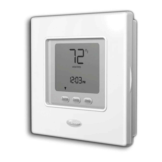
T2- -PHP01- - A, T2- - NHP01- -A
LEGACYt SERIES
THERMOSTATS
Installation Instructions
Legacy Series
Programmable Thermostat
NOTE: Read the entire instruction manual before starting the installation.
US patents: US20060165149 A1, USD582803 SI, USD582802 SI
A07047
Non- - Programmable Thermostat
Designed and Assembled in the U.S.A.
A07046
Legacy Series
Advertisement
Table of Contents


Need help?
Do you have a question about the T2-PAC01-A and is the answer not in the manual?
Questions and answers
I replaced the batteries now the unit doesn't come on.
If the Bryant T2-PAC01-A unit does not turn on after replacing the batteries, possible reasons include:
1. Improper Battery Installation: Ensure the new AA batteries are installed with the correct polarity, matching the "+" and "-" symbols in the battery compartment.
2. Dead Batteries: Verify that the replacement batteries are new and functional.
3. Incomplete Installation: Confirm that the thermostat is properly reattached to the wall bracket. Ensure the bottom slot and top latch are securely connected.
4. Damaged Thermostat or Wall Bracket: Inspect for damage to the thermostat or wall bracket that could prevent proper electrical contact.
If these steps do not resolve the issue, further troubleshooting may be required.
This answer is automatically generated
I have a T2-PAC01 need replacement, only find T2-PAC01-A in the internet, are they same?