Table of Contents
Advertisement
Quick Links
Advertisement
Table of Contents
Troubleshooting

Subscribe to Our Youtube Channel
Related Manuals for Elitegroup Computer Systems Z170-LIGHTSABER

Summary of Contents for Elitegroup Computer Systems Z170-LIGHTSABER
- Page 1 Z170-LIGHTSABER Version:1.0 40-012-KQ9100...
- Page 2 Shielded interconnect cables and a shielded AC power cable must be employed with this equipment to ensure compliance with the pertinent RF emission limits governing this device. Changes or modifications not expressly approved by the system’s manufacturer could void the user’s authority to operate the equipment. Z170-LIGHTSABER USER MANUAL...
- Page 3 Canadian Department of Communications This class B digital apparatus meets all requirements of the Canadian Interference- causing Equipment Regulations. Cet appareil numérique de la classe B respecte toutes les exigences du Réglement sur le matériel brouilieur du Canada. Z170-LIGHTSABER USER MANUAL...
- Page 4 Chapter 4 page 67 Describes the motherboard software. Using the Motherboard Software Chapter 5 Describes the AMD page 71 AMD Crossfire Technology Crossfire Technology. Support Chapter 6 page 75 Provides basic trouble Trouble Shooting shooting tips. Z170-LIGHTSABER USER MANUAL...
- Page 5 Memo Z170-LIGHTSABER USER MANUAL...
-
Page 6: Table Of Contents
The Standard Configuration...........29 Entering the Setup Utility............29 Resetting the Default CMOS Values........30 Using BIOS..................30 BIOS Navigation Keys..............31 Main Menu................32 Advanced Menu..............33 Chipset Menu................46 M.I.B.X (MB Intelligent BIOS X) Menu........53 Security Menu.................63 Boot Menu................64 Exit Menu................65 Updating the BIOS..............66 Z170-LIGHTSABER USER MANUAL... - Page 7 The Catalyst Control Center Dialog Box........73 To Enable CrossFire ..............73 Chapter 6 Trouble Shooting Start up problems during assembly..........75 Start up problems after prolong use..........76 Maintenance and care tips..............76 Basic Troubleshooting Flowchart...........77 POST Code Checkpoints Z170-LIGHTSABER USER MANUAL...
-
Page 8: Introducing The Motherboard
Chapter 1 Introducing the Motherboard Introduction Thank you for choosing the Z170-LIGHTSABER motherboard. This motherboard is a high performance, enhanced function motherboard designed to support the ® LGA1151 socket for Intel Skylake processor. ® ® ® ® ® This motherboard is based on Intel Z170 Express Chipset for best desktop platform solution. -
Page 9: Specifications
• 1 x RJ45 LAN connector • 1 x 8-ch Audio jacks Note: *The yellow ports only used for game USB 2.0 keyboard and mouse, while the red ports only used for rezound vigor USB 2.0 device. Z170-LIGHTSABER USER MANUAL... - Page 10 Add the function of copying BIOS parameters to USB flash drive Bundled • 3rd Party Bundled software: Cyberlink Media Suite* Software Note: *Free bundle software including ECS DVD: Cyberlink Media Suite Support Form Factor • ATX Size, 305mm x 244mm Z170-LIGHTSABER USER MANUAL...
-
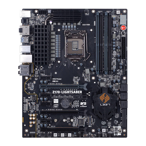
Page 11: Motherboard Components
Motherboard Components Z170-LIGHTSABER USER MANUAL... - Page 12 Quick OC button 23. PWR_FAN 4-pin Power cooling fan connector 24. F_AUDIO Front panel audio header 25. PCIEX16_1~3 PCI Express x16 Gen3 slots for graphics interface 26. PCIEX1_1~4 PCI Express x1 Gen3 slots 27. ATX_12V 8-pin +12V power connector Z170-LIGHTSABER USER MANUAL...
-
Page 13: I/O Ports
A, B, C and E port respectively. In addition, all of the 3 ports, B, C and E provide users with both right & left channels individually. Users please refer to the following note for specific port function definition. Z170-LIGHTSABER USER MANUAL... - Page 14 F75223 is backuping the file from SPIROM_B into SPIROM_A. Backup is finished if ROM_LED returns to remain on after 30s. 2. Disconnect AC for more than 30s, then push SPIROM_SW to side A, system will return to default state. Z170-LIGHTSABER USER MANUAL...
- Page 15 Your computer will fast reset after pressing this EZ RESET RESET button. EZ POWER POWER This is power button. This button is used to clear CMOS. Please EZ Clear CMOS CLR_CMOS_BTN perform this operation after disconnecting the AC PWR for more than 30s. Z170-LIGHTSABER USER MANUAL...
-
Page 16: Installing The Motherboard
Do not over-tighten the screws as this can stress the motherboard. When installing 24-pin ATX power cable, please note the overhead space because of the chassis design of the Motherboard, avoiding to damage the motherboard with excessive power. Z170-LIGHTSABER USER MANUAL... -
Page 17: Installing Hardware
Lift the tail of the load lever and rotate the load plate to fully open position. Grasp the edge of the package substrate. Make sure pin 1 indicator is on your bottom-left side. Aim at the socket and place the package carefully into the socket by purely vertical motion. Z170-LIGHTSABER USER MANUAL... - Page 18 Spreader). Engage the load lever while pressing down lightly onto the load plate. Secure the load lever with the hook under retention tab. Then the cover will flick automatically. Please save and replace the cover onto the CPU socket if processor is removed. Z170-LIGHTSABER USER MANUAL...
-
Page 19: Installing The Cpu Cooler
B. Fasten the cooling fan supporting base onto the CPU socket on the motherboard. And make sure the CPU fan is plugged to the CPU fan connector. C. Connect the CPU cooler power connector to the CPU_FAN connector. Z170-LIGHTSABER USER MANUAL... -
Page 20: Installing Memory Modules
The slot latche is levered upwards and latch on to the edges of the DIMM. The four DDR4 memory sockets (DIMM1, DIMM2, DIMM3 and DIMM4) are divided into two channels and each channel has two memory sockets as following: Channel A: DIMM1, DIMM2 Channel B: DIMM3, DIMM4 Z170-LIGHTSABER USER MANUAL... - Page 21 1. For best performance and compatibility, we recommend that users give priority to the DIMMs (DIMM2/DIMM4) when installing DIMMs. 2. We suggest users not to mix memory type. It is recommended to use the same brand and type memory on this motherboard. Z170-LIGHTSABER USER MANUAL...
-
Page 22: Installing Add-On Cards
Recommend add_on card configuration PCI Express operating mode VGA configuration PCIe 3.0 x16_1 (gray) PCIe 3.0 x16_2 PCIe 3.0 x16_3 x16 (Recommended Single VGA/PCIe card for single VGA card) Dual VGA/PCIe cards Triple VGA/PCIe cards Z170-LIGHTSABER USER MANUAL... - Page 23 Demount the screw not used according to the length of your M.2 SSD card. Insert the M.2 SSD card into M2_2208M slot in the fool-proof way. Lock the screw as the following picture shows to make sure the M.2 SSD card is installed in place. Z170-LIGHTSABER USER MANUAL...
-
Page 24: Connecting Optional Devices
2-3-5. Connecting Optional Devices Refer to the following for information on connecting the motherboard’s optional devices: Components Components USB3F F_USB1~2 SATA3_1~6 CASE SATAE_7/8 F_AUDIO Z170-LIGHTSABER USER MANUAL... - Page 25 A different pin assignment may cause damage or system hang-up. 2. SATA3_1~6: Serial ATA 6GB/s Connectors SATA3_1~6 connectors are used to support the Serial ATA 6Gb/s device, simpler disk drive cabling and easier PC assembly. Z170-LIGHTSABER USER MANUAL...
- Page 26 USB connector to connect the front-mounted ports to the motherboard. Please make sure that the USB cable has the same pin assignment as indicated above. A different pin assignment may cause damage or system hang-up. Z170-LIGHTSABER USER MANUAL...
- Page 27 The front panel audio header allows the user to install auxiliary front-oriented microphone and line-out ports for easier access. This header supports HD audio by default. If you want connect an AC’ 97 front panel audio to HD onboard headers, please set as below picture. Z170-LIGHTSABER USER MANUAL...
- Page 28 AC’97 Panel If you use HD Audio Front Panel, when you tick off “Disable Front Panel Detection ”, the front right two ports will highlight, then there is no jack detection function. HD Panel * For reference only Z170-LIGHTSABER USER MANUAL...
-
Page 29: Installing A Sata Hard Drive
Attach either cable end to the connector on the motherboard. Attach the other cable end to the SATA hard drive. Attach the SATA power cable to the SATA hard drive and connect the other end to the power supply. * For reference only Z170-LIGHTSABER USER MANUAL... -
Page 30: Connecting Case Components
2-3-7. Connecting Case Components After you have installed the motherboard into a case, you can begin connecting the motherboard components. Refer to the following: Components Components CPUFAN1~2 ATX_POWER PWR_FAN SYSFAN1~2 ATX_12V F_PANEL Z170-LIGHTSABER USER MANUAL... - Page 31 ~ 2.2A (26.4W max) at +12V. 2 & 7: ATX_POWER (ATX 24-pin Power Connector) & ATX_12V (8-pin ATX 12V Power Connector) Connect the standard power supply connector to ATX_POWER. Connect the auxiliary case power supply connector to ATX_12V. Z170-LIGHTSABER USER MANUAL...
- Page 32 8-pin power cable Connecting 4-pin power cable The ATX_12V power connector is used to provide power to the CPU. When installing 4-pin power cable, the latches of power cable and the ATX_12V match perfectly. 4-pin power cable Z170-LIGHTSABER USER MANUAL...
-
Page 33: Front Panel Header
50 ms to signal the power supply to switch on or off. The time requirement is due to internal de-bounce circuitry. After receiving a power on/off signal, at least two seconds elapses before the power supply recognizes another on/off signal. Z170-LIGHTSABER USER MANUAL... - Page 34 5. BZ: Buzzer Header This concludes Chapter 2. The next chapter covers the BIOS. Z170-LIGHTSABER USER MANUAL...
- Page 35 Memo Z170-LIGHTSABER USER MANUAL...
-
Page 36: Using Bios
When you power on the system, BIOS enters the Power-On Self Test (POST) routines. POST is a series of built-in diagnostics performed by the BIOS. After the POST routines are completed, the following message appears: Press DEL to enter SETUP Z170-LIGHTSABER USER MANUAL... -
Page 37: Resetting The Default Cmos Values
Other options lead to dialog boxes that prompt you for information. Some options (marked with an icon ) lead to submenus that enable you to change the values for the option. Use the cursor arrow keys to scroll through the items in the submenu. Z170-LIGHTSABER USER MANUAL... -
Page 38: Bios Navigation Keys
BIOS setup screens shown in this chapter are for reference only and may differ from the actual BIOS. Please visit the manufacture’s website for updated manual. 2. In this Gui BIOS, you can operate by mouse or keyboard. Click : select item; Double click: enter; Right click: exit. Z170-LIGHTSABER USER MANUAL... -
Page 39: Main Menu
The Date and Time items show the current date and time on the computer. If you are running a Windows OS, these items are automatically updated whenever you make changes to the Windows Date and Time Properties utility. Z170-LIGHTSABER USER MANUAL... -
Page 40: Advanced Menu
: Select Screen USB Configuration /Click: Select Item Super IO Configuration Enter/Dbl Click : Select Trusted Computing +/- : Change Opt. F1: General Help F2: Previous Values F3: Optimized Defaults F4: Save & Exit ESC/Right Click: Exit Z170-LIGHTSABER USER MANUAL... - Page 41 F1: General Help F2: Previous Values F3: Optimized Defaults F4: Save & Exit ESC/Right Click: Exit Onboard LAN Controller (Enabled) Use this item to enable or disable Onboard LAN controller. Press <Esc> to return to the Advanced Menu page. Z170-LIGHTSABER USER MANUAL...
- Page 42 F3: Optimized Defaults F4: Save & Exit ESC/Right Click: Exit Smart Fan Select (CPU Fan 1) This item allows you to change and configure Smart Fans on M/B. ex. CPU Fan1, CPU Fan 2, System Fan 1. Z170-LIGHTSABER USER MANUAL...
- Page 43 • Core Voltage • DIMM Voltage • VCCSA Voltage • VCCIO Voltage • PCH Voltage Press <Esc> to return to the Advanced Menu page. TCC Activation Temperature (DTS) (100) This item shows the factory TCC activation temperature. Z170-LIGHTSABER USER MANUAL...
- Page 44 EUP Function (Disabled) This item allows user to enable or disable EUP support. Power LED Type (Dual Color LED) This item shows the type of the Power LED. Press <Esc> to return to the Advanced Menu page. Z170-LIGHTSABER USER MANUAL...
- Page 45 F4: Save & Exit ESC/Right Click: Exit ACPI Sleep State [S3(Suspend to RAM)] This item allows user to enter the ACPI S3 (Suspend to RAM) Sleep State (default). Press <Esc> to return to the Advanced Menu page. Z170-LIGHTSABER USER MANUAL...
- Page 46 This item shows the computer supports Intel VT-x Technology. Hyper-threading (Enabled) This item is only available when the chipset supports Hyper-threading and you are using a Hyper-threading CPU. Active Processor Cores (All) Use this item to control the number of active processor cores. Z170-LIGHTSABER USER MANUAL...
- Page 47 Use this item to enable the CPU energy-saving function when the system is not running. Intel(R) Speed Shift Technology (Disabled) Use this item to enable or disable the Intel(R) Speed Shift Technology. Press <Esc> to return to the Advanced Menu page. Z170-LIGHTSABER USER MANUAL...
- Page 48 Use these items to configure each device on the SATA channel. Spin Up Device (Disabled) Use this item to enable or disable the spin up device. External SATA (Disabled) Use this item to enable or disable the external SATA. Z170-LIGHTSABER USER MANUAL...
- Page 49 ASM1061 Chip), each channel allows one SATA device to be installed. Use these items to configure each device on the SATA channel. Press <Esc> to return to the SATA Configuration page. Press <Esc> to return to the Advanced Menu page. Z170-LIGHTSABER USER MANUAL...
- Page 50 Legacy USB Support (Enabled) Use this item to enable or disable support for legacy USB devices. USB3.1 Controller (Enabled) Use this item to enable or disable USB3.1 controller. Press <Esc> to return to the Advanced Menu page. Z170-LIGHTSABER USER MANUAL...
- Page 51 F1: General Help F2: Previous Values F3: Optimized Defaults F4: Save & Exit ESC/Right Click: Exit Super IO Chip (IT8733) This item shows the information of the super IO chip. Press <Esc> to return to the Advanced Menu page. Z170-LIGHTSABER USER MANUAL...
- Page 52 TPM2.0 UEFI Spec Version (1.0) Use this item to show the TPM2.0 UEFI Spec Version. TPM 20 InterfaceType (CRB) Use this item to show the TPM 20 InterfaceType. Press <Esc> to return to the Advanced Menu page. Z170-LIGHTSABER USER MANUAL...
-
Page 53: Chipset Menu
When set to Fixed Mode, the graphics driver will reserve a fixed position of the system memory as graphics memory. When set to DVMT Mode, the graphics chip will dynamically allocate system memory as graphics memory, according to system and graphics requirements. Z170-LIGHTSABER USER MANUAL... - Page 54 Windows 7/8/8.1. Step 1. Insert ECS drives DVD to run Auto setup or browse the DVD to install Intel chipset drivers, VGA and sound drivers.(If you want know the detail information, please refer to chapter 4.) Z170-LIGHTSABER USER MANUAL...
- Page 55 256M Device. IGD Multi-Monitor Disabled : Select Screen /Click: Select Item Enter/Dbl Click : Select +/- : Change Opt. F1: General Help F2: Previous Values F3: Optimized Defaults F4: Save & Exit ESC/Right Click: Exit Z170-LIGHTSABER USER MANUAL...
- Page 56 Extend desktop to this display You must select Apply before making additional changes. Disconnect this display Make this my main display Advance settings Make text and other items larger or smaller What display settings should I choose? Cancel Apply Z170-LIGHTSABER USER MANUAL...
- Page 57 Multiple displays: Extend desktop to this display You must select Apply before making additional changes. Make this my main display Advance settings Make text and other items larger or smaller What display settings should I choose? Cancel Apply Z170-LIGHTSABER USER MANUAL...
- Page 58 This item enables or disables the warning if the case is opened up, and the item below indicates the current status of the case. Chassis Opened (No) This item indicates whether the case has been opened. Press <Esc> to return to the Chipset Menu page. Z170-LIGHTSABER USER MANUAL...
- Page 59 F4: Save & Exit ESC/Right Click: Exit ME Control (Enabled) Use this item to enable or disable the ME Firmware. ME FW Version (11.0.0.1202) This item shows the ME FW version. Press <Esc> to return to the Chipset Menu page. Z170-LIGHTSABER USER MANUAL...
-
Page 60: Mb Intelligent Bios X) Menu
Core 4 Ratio Limit F3: Optimized Defaults F4: Save & Exit Ring Max OC Ratio ESC/Right Click: Exit BCLK (1/100 MHz) 10000 EIST (Enabled) This item allows users to enable or disable the EIST (Enhanced Intel SpeedStep Technology). Z170-LIGHTSABER USER MANUAL... - Page 61 Use this item to enable or disable the power limit 3 override. If this option is disabled, BIOS will leave the default values for power limit 3 and power limit 3 time window. Press <Esc> to return to the CPU OverClocking Configuration page. Z170-LIGHTSABER USER MANUAL...
- Page 62 Ring Max OC Ratio (0) Use this item to set the Ring Max OC Ratio value. BCLK (1/100 MHz) (10000) Use this item to set the BCLK (1/100 MHz) value. Press <Esc> to return to the M.I.B. X Menu page. Z170-LIGHTSABER USER MANUAL...
- Page 63 /Click: Select Item Enter/Dbl Click : Select Advanced Timing Configuration +/- : Change Opt. tCKE F1: General Help tRDRD_dr F2: Previous Values tRDRD_dd F3: Optimized Defaults tRDRD_sg F4: Save & Exit tRDRD_dg ESC/Right Click: Exit tWRWR_dr tWRWR_dd Z170-LIGHTSABER USER MANUAL...
- Page 64 Use this item to enable or disable the exit on failure (MRC). Mc Lock (Enabled) This item allows you to enable or disable capacity to lock MC registers or not. Ch Hash Support (Enabled) Use this item to enable or disable the Ch Hash support. Z170-LIGHTSABER USER MANUAL...
- Page 65 This item allows you to enable or disable 2xRef when warm and Hot 2-iMC enables 2xRef when Hot. SelfRefresh Enable (Enabled) Use this item to enable or disable the SelfRefresh. Press <Esc> to return to the M.I.B. X Menu page. Z170-LIGHTSABER USER MANUAL...
- Page 66 F2: Previous Values F3: Optimized Defaults F4: Save & Exit ESC/Right Click: Exit GT OverClocking Frequency (0) This item allows you to adjust the GT OverClocking frequency. Press <Esc> to return to the M.I.B. X Menu page. Z170-LIGHTSABER USER MANUAL...
- Page 67 This item allows you to adjust the Uncore/Ring/GT voltage offset from -1000 to 998mV. Offset Prefix (+) This item allows you to select the offset value as positive (+) or negative (-). Press <Esc> to return to the M.I.B. X Menu page. Z170-LIGHTSABER USER MANUAL...
- Page 68 Use this item to save BIOS setup data to profile. Restore last setting (Disabled) This item allows you to enable or disable to restore the last setting. Press <Esc> to return to the M.I.B. X Menu page. Z170-LIGHTSABER USER MANUAL...
- Page 69 2. Press and hold the “Page Up Key (PgUp)” of the keyboard, and then boot the PC 3. Two seconds after the PC boots up, release the “Page Up Key (PgUp)”. 4. The BIOS returns to the default setting by itself. Z170-LIGHTSABER USER MANUAL...
-
Page 70: Security Menu
Secure Boot state (Not Active) This item allows you to enable or disable the secure boot state. Secure Boot (Disabled) This item is used to control the secure boot flow, it is possible only if system runs in User Mode. Z170-LIGHTSABER USER MANUAL... -
Page 71: Boot Menu
Boot Option #1 /2 /3 /4 /5 /6 /7 These items show the boot priorities. USB Flash Drive Priorities This item enables you to specify the sequence of loading the operating system from the installing USB Flash drives. Z170-LIGHTSABER USER MANUAL... -
Page 72: Exit Menu
Discard Changes This item enables you to discard any changes that you have made. Restore Defaults This item enables you to restore defaults to all the setup options. Boot Override Use this item to select the boot device. Z170-LIGHTSABER USER MANUAL... -
Page 73: Updating The Bios
BIOS jumper, reset the jumper to protect the newly installed BIOS from being overwritten. The computer will restart automatically. This concludes Chapter 3. Refer to the next chapter for information on the software supplied with the motherboard. Z170-LIGHTSABER USER MANUAL... -
Page 74: Using The Motherboard Software
Click Setup. The installation program begins: The following screens are examples only. The screens and driver lists will be different according to the motherboard you are installing. The motherboard identification is located in the upper left-hand corner. Z170-LIGHTSABER USER MANUAL... - Page 75 Windows 8 will show the following screen after system restart, you must select “Desktop” in the bottom left to install the next driver. Z170-LIGHTSABER USER MANUAL...
-
Page 76: Manual Installation
If the driver you want to install does not have a setup program, browse to the oper- ating system subfolder and locate the readme text file (README.TXT or README.DOC) for information on installing the driver or software for your operating system. Z170-LIGHTSABER USER MANUAL... - Page 77 Memo Z170-LIGHTSABER USER MANUAL...
-
Page 78: Amd Crossfire Tm Technology Support
PCIEX16_1~3 slots. Make sure that the card is properly seated on the slot. A. For 2-way configuration, install two graphic cards on PCIEX16_1 and PCIEX16_2, then connect them with the CrossFire Bridge. * For reference only Z170-LIGHTSABER USER MANUAL... - Page 79 2. Connect the cable from your monitors to the CrossFireX ready graphics card installed on the PCIEX16 slot. Monitor Cable * For reference only 3. Connect an auxiliary power source from the power supply to the graphics cards. Z170-LIGHTSABER USER MANUAL...
-
Page 80: The Catalyst Tm Control Center Dialog Box
The Catalyst Control Center Dialog Box To enable CrossFireX • Install AMD graphic card driver. • Enter the Catalyst Control Center Dialog Box. • check the “Enable CrossFireX ” item. • Click Apply button. Z170-LIGHTSABER USER MANUAL... - Page 81 Memo Z170-LIGHTSABER USER MANUAL...
-
Page 82: Trouble Shooting
1. The CPU may experience overheating so it will shutdown to protect itself. Apply the thermal grease onto the CPU heatsink & ensure the CPU fan is well-connected with the CPU heatsink. Check if the CPU fan is working properly while the system is running. Z170-LIGHTSABER USER MANUAL... -
Page 83: Start Up Problems After Prolong Use
6. If possible, ensure the power cord has an earth ground pin directly from the wall outlet. This will reduce voltage fluctuation that may damage sensitive devices. Z170-LIGHTSABER USER MANUAL... - Page 85 Memo Z170-LIGHTSABER USER MANUAL...
-
Page 86: Post Code Checkpoints
Memory initialization. Programming memory timing information Memory initialization. Configuring memory Memory initialization (other). Reserved for ASL (see ASL Status Codes section below) Memory Installed CPU post-memory initialization is started CPU post-memory initialization. Cache initialization CPU post-memory initialization. Application Processor(s) (AP) initialization Z170-LIGHTSABER USER MANUAL... - Page 87 Recovery condition triggered by user (Forced recovery) Recovery process started Recovery firmware image is found Recovery firmware image is loaded F5-F7 Reserved for future AMI progress codes Recovery PPI is not available Recovery capsule is not found Invalid recovery capsule Z170-LIGHTSABER USER MANUAL...
- Page 88 PCI Bus Hot Plug Controller Initialization PCI Bus Enumeration PCI Bus Request Resources PCI Bus Assign Resources Console Output devices connect Console input devices connect Super IO Initialization USB initialization is started USB Reset USB Detect USB Enable Z170-LIGHTSABER USER MANUAL...
- Page 89 Flash update is failed Reset protocol is not available Platform PCI resource requirements cannot be met System is entering S1 sleep state System is entering S2 sleep state System is entering S3 sleep state System is entering S4 sleep state Z170-LIGHTSABER USER MANUAL...
Need help?
Do you have a question about the Z170-LIGHTSABER and is the answer not in the manual?
Questions and answers