Table of Contents
Advertisement
Quick Links
UM2872
User manual
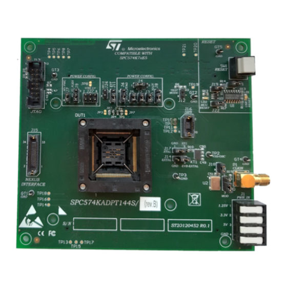
SPC574KADPT144S Rev. B evaluation board
Introduction
The SPC574KADPT144S Rev. B mini module is an evaluation board supporting STMicroelectronics SPC574K7XE5 device in
ETQFP144 package.
Figure 1.
SPC574KADPT144S Rev. B
UM2872 - Rev 1 - May 2021
www.st.com
For further information contact your local STMicroelectronics sales office.
Advertisement
Table of Contents

Subscribe to Our Youtube Channel
Related Manuals for ST SPC574KADPT144S


Summary of Contents for ST SPC574KADPT144S
- Page 1 UM2872 User manual SPC574KADPT144S Rev. B evaluation board Introduction The SPC574KADPT144S Rev. B mini module is an evaluation board supporting STMicroelectronics SPC574K7XE5 device in ETQFP144 package. Figure 1. SPC574KADPT144S Rev. B UM2872 - Rev 1 - May 2021 www.st.com For further information contact your local STMicroelectronics sales office.
-
Page 2: Overview
High density connectors provide the interface between the EVB and MCU daughter cards and help the developers to evaluate all device peripherals. This user manual provides information on using SPC574KADPT144S Rev. B mini module board and its hardware features. -
Page 3: Figure 3. Overview Of Spc574Kadpt144S - Bottom
UM2872 Overview Figure 3. Overview of SPC574KADPT144S - bottom UM2872 - Rev 1 page 3/31... -
Page 4: License Agreement
Attention: This evaluation board only offers limited features for evaluating ST products. It has not been tested for use with other products and is not suitable for any safety or other commercial or consumer application. This evaluation board is otherwise provided “AS IS”... -
Page 5: Handling Precautions
UM2872 Handling precautions Handling precautions Please take care to handle the package content in order to prevent electrostatic discharge. Before the EVB is used or power is applied, please fully read the following sections on how to correctly configure the board. Failure to correctly configure the board may cause irreparable component, MCU or EVB damage. UM2872 - Rev 1 page 5/31... -
Page 6: Features
UM2872 Hardware description Hardware description Hardware features The SPC574KADPT144S Rev. B mini module board has the following features: • It can be used as a stand-alone board by providing external power supplies input (5 V, 3.3 V, 1,25 V) •... -
Page 7: Figure 5. Overview Of 6-Pin Jumper Numbering Convention
UM2872 Pin numbering for jumpers Figure 5. Overview of 6-pin jumper numbering convention UM2872 - Rev 1 page 7/31... -
Page 8: Hardware And Jumper Setting
NOT be used. When the SPC574KADPT144S Rev. B mini module is used as a stand-alone board , the external power supplies must be used (5 V, 3.3 V, 1,25 V). - Page 9 Power supplies Jumper Description Default Position VDD_HV_IO_FLEX voltage Figure 10. Overview of configuration: 1-2 (5V_SR) SPC574KADPT144S Rev. • 1-2: 5V_SR B mini module - top – B2 • 2-3: 3.3V_SR Jumper to enable the external core voltage supply Figure 10. Overview of •...
-
Page 10: Jtag/Lfast Lvds/ Sipi Interface Configuration
Jumper Description Default Position PA[8] connection to QSH connectors configuration: • Open: PA[8] not connected to QSH connectors Figure 10. Overview of SPC574KADPT144S Open (motherboard) Rev. B mini module - top – B2 • Closed: PA[8] connected to QSH PA[9] connection to QSH connectors configuration: •... -
Page 11: System Clock Configuration
EXTAL connection configuration: • 1-2: EXTAL connected to 40 MHz crystal clock Figure 10. Overview of source 1-2 (XT1 pin 1) SPC574KADPT144S Rev. B mini module top– C3 • 2-3: EXTAL connected to EXTAL EVB clock source XTAL connection configuration: Figure 10. -
Page 12: Reset Circuit
Table 5. Connectors Conn ector Description Position Figure 10. Overview of SPC574KADPT144S Rev. B mini External power supplies input module - top – D4 Figure 10. Overview of SPC574KADPT144S Rev. B mini 14-pin header connector for JTAG port module - top –... -
Page 13: Table 7. Jtag Header 2 X 7 Pins Connector Pinout
UM2872 Connectors Figure 7. JTAG connector schema The following table shows the JTAG connector pinout. Table 7. JTAG header 2 x 7 pins connector pinout Pin number Signal EVTI PORST ESR0 VDD_HV_IO_MAIN EVTO N.C. The following picture shows the NEXUS SAMTEC ASP-137973-01 connector schema. UM2872 - Rev 1 page 13/31... -
Page 14: Table 8. Nexus Samtec Asp-137973-01 Connector Pinout
UM2872 Connectors Figure 8. NEXUS SAMTEC ASP-137973-01 The following table shows the NEXUS SAMTEC ASP-137973-01 connector pinout. Table 8. NEXUS SAMTEC ASP-137973-01 connector pinout Pin number Signal N.C. 3.3 V N.C. TX1P TX1N UM2872 - Rev 1 page 14/31... - Page 15 UM2872 Connectors Pin number Signal JCOMP N.C. N.C. N.C. EVTI EVTO N.C. PORST N.C. ESR0 N.C. N.C. N.C. N.C. N.C. N.C. N.C. N.C. The following figure shows the SIPI interface schema. UM2872 - Rev 1 page 15/31...
-
Page 16: Test Points
SIPI_RXP Test points Several test points of different shape and functionality are scattered around the SPC574KADPT144S Rev. B evaluation board to allow easy access to MCU and reference signals. This chapter summarizes and describes the available test points. Test points are listed and detailed in the following table. -
Page 17: Figure 10. Overview Of Spc574Kadpt144S Rev. B Mini Module - Top
Test points Test Point Description Position VSS_OSC test point Figure 10. Overview of SPC574KADPT144S Rev. B mini module - top – D3 AGND test point Figure 10. Overview of SPC574KADPT144S Rev. B mini module - top– C3 JCOMP test point (JTAG) Figure 10. -
Page 18: Layout Overview
UM2872 Layout overview Layout overview Figure 10. Overview of SPC574KADPT144S Rev. B mini module - top UM2872 - Rev 1 page 18/31... -
Page 19: Figure 11. Overview Of Spc574Kadpt144S Rev. B Mini Module - Bottom
UM2872 Layout overview Figure 11. Overview of SPC574KADPT144S Rev. B mini module - bottom UM2872 - Rev 1 page 19/31... -
Page 20: Bom
C49, C50 10pF Mult. Cer. cap. 50 V SMD 0603 K2 - Device Under Test ZOCC144ET DUT1 ETQFP144_X - ETQFP144(X6) - ENPLAS OTQ-144SG-0.5-003 for ST GT1, GT2, GT3, GT4, PCB test point - Raised Loops, TEST2 TEST2 GT5, TP2, Testpoint SMD... - Page 21 UM2872 Item Reference Value Option Description CONNERF80 SAMTEC 0.8 mm pitch Rugged High 5X2-SMD Speed SMD Connector STRIP 3 Close pin 2 STRIP3PM Male Strip 3 poles See Mech Part POLI and 3 STRIP 2 J18, J26 STRIP2PM Open Male Strip 2 poles See Mech Part POLES SAM- QSH-120-01-...
- Page 22 UM2872 Item Reference Value Option Description 74V1G08- 74V1G08 I.C. Single 2-In AND gate SOT23-5L Q40MHZ- Quartz 40MHz SMD NX5032GA SMD-5032 XTAL NDK UM2872 - Rev 1 page 22/31...
-
Page 23: Schematics
Schematics Figure 12. Power and decoupling Po w e r a n d De c o u p l i n g 5.0V_LR 3.3V_SR 5.0V_SR 1.25V_SR 49R9 VDD_HV_ADR_S 0805 default CLOSED 2.2uF 100nF 1000pF 1.25V_SR 3.3V_SR 5.0V_SR 0805 0603 0603 DEFAULT 1-2 CLOSED AGND... -
Page 24: Figure 13. Signals
Figure 13. Signals JCOMP S i g n a l s JCOMP PA[0..15] PA[0..15] PE[0..15] PE[0..15] DUT1B SIPI_TXN PA[0] PE[0] SIPI_TXN PA[1] PE[1] PA[2] PE[2] TP10 PA[3] PE[3] PA[4] PE[4] PA[5] PE[5] SIPI_TXP PA[6] PE[6] SIPI_TXP PA[7] PE[7] PA[8] PE[8] TP11 PA[9] PE[9]... -
Page 25: Figure 14. Reset Jtag, Sipi, Nexus Interface And Crystal Oscillator
Figure 14. Reset JTAG, SIPI, Nexus interface and crystal oscillator VDD_HV_IO_JTAG VDD_HV_IO_JTAG Jtag interface Re s e t , J TAG, S IPI a n d Cr y s t a l Os c i l l a t or VDD_HV_IO_JTAG JTAG Connector 0R DNP... -
Page 26: Figure 15. Doughter Card And Motherboard Connectors
Figure 15. Doughter card and motherboard connectors DAUGHTER CARD TO MOTHERBOARD CONNECTORS PortA PortB PortC PortD PortF PortG PortH PortE PA[0..15] PB[0..15] PC[0..15] PD[0..15] PE[0..15] PF[0..15] PG[1..15] PH[0..4] PA[0..15] PB[0..15] PC[0..15] PD[0..15] PE[0..15] PF[0..15] PG[1..15] PH[0..4] PortI PA10 PB10 PC10 PD10 PE10 PF10... -
Page 27: Revision History
UM2872 Revision history Table 12. Document revision history Date Version Changes 26-May-2021 Initial release. UM2872 - Rev 1 page 27/31... -
Page 28: Table Of Contents
UM2872 Contents Contents Overview ................2 License agreement . - Page 29 UM2872 List of tables List of tables Table 1. Power supplies configuration jumpers............8 Table 2.
- Page 30 Overview of SPC574KADPT144S Rev. B mini module - bottom ....... .
- Page 31 ST’s terms and conditions of sale in place at the time of order acknowledgement. Purchasers are solely responsible for the choice, selection, and use of ST products and ST assumes no liability for application assistance or the design of Purchasers’...
Need help?
Do you have a question about the SPC574KADPT144S and is the answer not in the manual?
Questions and answers