
Subscribe to Our Youtube Channel
Related Manuals for Advantech UBC-220


Summary of Contents for Advantech UBC-220
- Page 1 User Manual UBC-220 RISC IoT Box Computer Powered by Freescale i.MX6 Dual Lite Processor ARM® Cortex™ A9 Architecture...
- Page 2 No part of this manual may be reproduced, copied, translated or transmitted in any form or by any means without the prior written permission of Advantech Co., Ltd. Information provided in this manual is intended to be accurate and reliable. How- ever, Advantech Co., Ltd.
- Page 3 Consult the dealer or an experienced radio/TV technician for help. Technical Support and Assistance Visit the Advantech website at http://support.advantech.com where you can find the latest information about the product. Contact your distributor, sales representative, or Advantech's customer service center for technical support if you need additional assistance.
- Page 4 This product is intended to be supplied by a Listed Power Adapter or DC power source marked “L.P.S.”, rated 12Vdc, 3A minimum, Tma = 40 degree C. If need further assistance, please contact Advantech for fur- ther information. UBC-220 User Manual...
- Page 5 Caution! There is a danger of a new battery exploding if it is incorrectly installed. Do not attempt to recharge, force open, or heat the battery. Replace the battery only with the same or equivalent type recommended by the man- ufacturer. Discard used batteries according to the manufacturer's instructions. UBC-220 User Manual...
- Page 6 UBC-220 User Manual...
-
Page 7: Table Of Contents
System Dimensions ..............17 Figure 2.17System Dimension Layout (Top Side) ...... 17 Figure 2.18System Dimension Layout (Bottom Side)....18 Figure 2.19System Dimension Layout (Coastline) ..... 18 Quick Start of UBC-220................18 2.4.1 Debug Port Connection............... 18 2.4.2 Debug Port setting ..............18 Figure 2.20Hyper Terminal Settings for Terminal Setup .... - Page 8 3.6.2 Boot from Onboard Flash ............35 Debug Message..................36 Figure 3.3 HyperTerminal Settings for Serial Console Setup..36 Linux Software AP and Testing on UBC-220.......... 36 3.8.1 “Hello World!” Application and Execution ........37 3.8.2 Watchdog Timer Sample Code........... 37 3.8.3...
-
Page 9: Chapter 1 General Introduction
Chapter General Introduction This chapter gives background information on the UBC-220. Sections include: Introduction Product Features Specifications... -
Page 10: Introduction
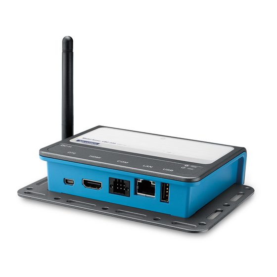
Introduction UBC-220 is a compact box computer powered by Freescale i.MX6 Dual Lite high per- formance CPU, it is an ideal solution for IoT, automation and HMI applications. The User manual covers two parts: Hardware I/O specifications and software introduc- tion. -
Page 11: Electrical Specifications
Operating temperature: 0 ~ 40 ° C (32 ~ 140 ° Operating humidity: 40 ° C @ 95% RH Non-condensing Storage temperature: -40 ~ 85 ° C (-40 ~ 185 ° C) Storage humidity: 60 ° C @ 95% RH Non-condensing Block Diagram UBC-220 User Manual... - Page 12 UBC-220 User Manual...
-
Page 13: Chapter 2 H/W Installation
Chapter H/W Installation This chapter introduces the startup procedures of the UBC- 220 hardware, including jumper setting and device integration. It also introduces the setting of switches, indicators and also shows the mechanical drawings. Be sure to read all safety precau- tions before you begin installation procedure. -
Page 14: Jumpers
Generally, you simply need a standard cable to make most connections. Warning! To avoid damaging the computer, always turn off the power supply before setting jumpers. 2.1.2 Jumper List Table 2.1: Jumper List Boot Device LVDS_VDD_SLT LVDS Power LVDS_BKLT_SLT Backlight Power UBC-220 User Manual... -
Page 15: Jumper Settings
HD_3x1P_100_D Description PIN HEADER 3x1P 2.54mm 180D(M) DIP 205-1x3GS Setting Function (1-2) +V3.3 (2-3) LVDS_BKLT_SLT LVDS Backlight Power Part Number 1653003100 Footprint HD_3x1P_100_D Description PIN HEADER 3x1P 2.54mm 180D(M) DIP 205-1x3GS Setting Function (1-2) (2-3) +VIN (+12V) UBC-220 User Manual... -
Page 16: Connectors
LVDS_BKLT_PWR Backlight 2.2.2 Connector Settings 2.2.2.1 RTC Battery Connector (CN1) UBC-220 supports a lithium 3V/210mAH CR2032 battery with wire via battery con- nector. 2.2.2.2 Half-size MiniPCIe (MINI_PCIE_HALF) UBC-220 supports half size miniPCIe slot both USB and PCIe interface. Signal Name Signal Name 3.3Vaux... - Page 17 3.3VAUX Figure 2.1 Half-size miniPCIE 2.2.2.3 Full-size MiniPCIe (MINI_PCIE_FULL)) RSB-3410 supports full size miniPCIe slot which supports USB interface only. Table 2.2: Full-size miniPCIE Description Description +3.3V Reserved Reserved UIM_PWR UIM_DATA USB_DATA- Reserved UIM_CLK USB_DATA+ Reserved UIM_RESET UBC-220 User Manual...
- Page 18 Reserved PERST Reserved +3.3V Reserved +3.3V 2.2.2.4 SIM Socket (SIM_SLOT) UBC-220 supports on board SIM socket is for 3G integration. Please insert valid SIM card to dial to 3G network. Signal Name Signal Name UIM_PWR UIM_RESET UIM_CLK UIM_DATA Figure 2.2 Full-size miniPCIE...
- Page 19 Figure 2.3 SIM Socket 2.2.2.5 UART1 Debug Port (DEBUG_CONSOLE) UBC-220 can communicate with a host server (Windows or Linux) by using serial cables. Description +V3.3 DEBUG_TXD DEBUG_RXD Figure 2.4 Debug Port 2.2.2.6 USB Type A Connector (USB_HOST) UBC-220 supports one standard USB2.0 Type A connector in the coastline.
- Page 20 2.2.2.7 Ethernet Connector (LAN) UBC-220 provides one RJ45 LAN interface connector, it is fully compliant with IEEE 802.3u 10/100/1000 Base-T CSMA/CD standards. The Ethernet port provides stan- dard RJ-45 jack connector with LED indicators on the front side to show Active/Link status and Speed status.
- Page 21 HDMI_TD1+ HDMI_TD1- HDMI_TD0+ HDMI_TD0- HDMI_CLK+ HDMI_CLK- HDMI_CEC_A DDC_CLK_HDMI_A DDC_DATA_HDMI_A +5V_HPD HDMI_HP Figure 2.8 HDMI 2.2.2.10 USB OTG (USB_OTG) UBC-220 supports USB-OTG mode that can be taken to replace UART debug con- sole. Description USB Data- USB Data+ UBC-220 User Manual...
- Page 22 Figure 2.9 USB OTG 2.2.2.11 SD Slot UBC-220 supports SD/MMC card in Class2, 4, 6, 8, 10. Supported capacity is up to 32G (SDHC) Signal Name DAT3 +3.3V DAT0 DAT1 DAT2 Figure 2.10 SD Slot 2.2.2.12 COM Port UBC-220 provides one 6-pin terminal block connector as serial communication inter- face port.
- Page 23 2.2.2.13 LVDS Connector UBC-220 provides a LVDS 10x2-pin board-to-board connector for single channel 18/ 24 bit LVDS panel up to 1366x768. Please also refer to jumper setting in page 7 before connecting LVDS panel. Description LVDS0_TX0_P I2C1_SCL_LVDS0 LVDS0_TX0_N I2C1_SDA_LVDS0 LVDS0_TX1_P...
-
Page 24: Mechanical
Please also refer to jumper setting in page 7 before connecting LVDS panel. Description +VDD_BKLT_LVDS LCD_BKLT_A LCD_BKLT_PWM_A Figure 2.13 LVDS Backlight Connector Mechanical 2.3.1 Jumper and Connector Locations LVDS Jumper SIM Slot Backlight Jumper Full size Half size Mini-PCIe Mini-PCIe HDMI Figure 2.14 Jumper and Connector Layout (Top side) UBC-220 User Manual... -
Page 25: System Dimensions
LVDS Debug LVDS Backlight Port SD Slot Figure 2.15 Jumper and Connector Layout (Bottom Side) Figure 2.16 Coastline Layout 2.3.2 System Dimensions 2.3.2.1 System Drawing unit: mm Figure 2.17 System Dimension Layout (Top Side) UBC-220 User Manual... - Page 26 Figure 2.18 System Dimension Layout (Bottom Side) Figure 2.19 System Dimension Layout (Coastline) Figure 2.20 Mounting Method of UBC-220 UBC-220 User Manual...
-
Page 27: Quick Start Of Ubc-220
Open Hyper Terminal on your Windows PC, and select the settings as shown in Figure 3.6. After the bootloader is programmed on SD card, insert power adapter connector to DC jack on UBC-220 to power up the board. The bootloader prompt is dis- played on the terminal screen. UBC-220 User Manual... -
Page 28: Test Tools
Figure 2.23 Hyper Terminal Settings for Terminal Setup Test Tools All test tools must be verified on UBC-220, please prepare required test fixtures before verifying each specified I/O. If you have any problems to get the test fixture, please contact Advantech for help. -
Page 29: Sd Test
#hexdump -C /dev/mmcblk1 -s 25720832 -s 32 01887800 31 32 33 34 35 36 37 38 39 41 42 43 44 45 46 0a |123456789ABCDEF.| 01887810 1d 4f e2 19 d3 05 8b df ab 4a 40 5a c5 23 3c f2 UBC-220 User Manual... -
Page 30: Lvds/Hdmi Test
#gst-launch playbin2 uri=file:///tools/Advantech.avi video-sink="mfw_v4lsink device=/dev/video16"& You can see display independent both show Advantech.avi at the same time. If you’d like to set the output audio as HDMI out, please add the parameter of plughw: A. Plughw:1-->Output the audio through HDMI. -
Page 31: Led Test
1 > export cd /sys/class/gpio/gpio1 LED on echo 0 > value LED off echo 1 > value 2.5.7 OpenGL Test Please follow below instructions to test OpenGL on UBC-220 platform: Change path to /opt/viv_samples/vdk #cd /opt/viv_samples/vdk #ls tutorial* tutorial1 tutorial2_es20 tutorial4 tutorial5_es20... - Page 32 Run tutorial3_es20 for OpenGL ES 2.0 A ball made of a mirroring material and centered at the origin spins about its Y-axis and reflects the scene surrounding it. #./tutorial3_es20 UBC-220 User Manual...
-
Page 33: Lan Test
If you would like to config IP manually, please use below command: #ifconfig eth0 xxx.xxx.xxx.xxx up Here is a real case for your reference.The hosts (UBC-220) IP is 172.17.21.97; the target(A desktop computer) IP is 172.17.20.192 #ifconfig eth0 172.17.21.97 up... -
Page 34: Rs232 Test
2.5.9 RS232 Test As you can see below, there are 2 RS-232 supported by UBC-220. /dev/ttymxc0 is reserved for UBC-220 debug port (UBC-220 DEBUG_CONSOLE), the other one could be applied by the user. #setserial -g /dev/ttymxc* /dev/ttymxc0, UART: undefined, Port: 0x0000, IRQ: 58 /dev/ttymxc1, UART: undefined, Port: 0x0000, IRQ: 59 Below test was done with four 2.54mm pitch mini jumpers. -
Page 35: Led Test
2.5.12 LED Test Below is the test script for system LED2. #cd /sys/class/gpio/ #echo 1 > export #cd /sys/class/gpio/gpio1 LED on #echo 0 > value LED off #echo 1 > value UBC-220 User Manual... - Page 36 UBC-220 User Manual...
-
Page 37: Software Functionality
Chapter Software Functionality This chapter details the Linux operating system on the UBC-220 platform. -
Page 38: Introduction
Ubuntu 10.04 LTS installed to your host PC before start UBC-220 evaluation/development. Package Content We can offer you two different kinds of Linux package for UBC-220. One is a pre- built system image for system recovery another is source code package (BSP). 3.2.1... - Page 39 -->The administrative user's home directory. Mind the difference - root between /, the root directory and /root, the home directory of the root user. - sbin -->Programs for use by the system and the system administrator. - sys --> Linux sys file system UBC-220 User Manual...
- Page 40 - tools -->just for sample test. 3.2.1.5 scripts Some scripts provided by Advantech will help you configure system or build the images more quickly. Please check them as follows: - setenv.sh --> A script to setup the developing environment quickly.
-
Page 41: Set Up Build Environment
All instructions in this guide are based on Ubuntu 10.04 LTS developing environment. Please install the Ubuntu 10.04 LTS at your PC/NB in advance. When you obtain the UBC-220 Linux source code package, please refer to following instructions to extract to your developing environment: Copy "U220LBV2660"... -
Page 42: Build Instructions
This section will guide you how to build the u-boot & Linux kernel. 3.4.1 Build u-boot Image Advantech has written a script to build the u-boot quickly. You can build u-boot image by follow below steps: Open "Terminal" on Ubuntu 10.04 LTS.. -
Page 43: Source Code Modification
$sudo su (Change to “root” authority) Input user password. Change directory to BSP's scripts folder. #. setenv.sh (To configure the developing environment automatically) #./cfg_kernel.sh menuconfig Then you will see a GUI screen (Linux Kernel Configuration) as below: Figure 3.1 Linux Kernel Configuration UBC-220 User Manual... - Page 44 Please refer to former Chapter 3.3.2 to rebuild the kernel with RTC driver (Seiko Instruments S-35390A) after completing above steps. Note! If you cannot find the driver for your device from the list, please contact your hardware vender. UBC-220 User Manual...
-
Page 45: Chang Ubc-220 Boot Logo
Change directory to BSP's scripts folder. #./mksd-linux.sh /dev/sdf Type “y” (Start to copy files, wait until it shows [Done]) Then insert the Linux system SD card to UBC-220 SD card slot (SD1), it will boot up with Linux environment. 3.6.2 Boot from Onboard Flash If you’ve already had a Linux system SD card, you can refer following steps to copy... -
Page 46: Debug Message
Then you can boot from onboard flash without SD card. Debug Message UBC-220 can connect to a host PC (Linux or Windows) by using console cable and debug port adapter. In order to communicate with host PC, serial communication pro- gram such as HyperTerminal, Tera Term or PuTTY is must required. -
Page 47: Hello World!" Application And Execution
Insert the Linux system SD card to your developing computer. #cp helloworld /media/rootfs/tool (/media/rootfs is the mounted point of your Linux system SD card) Remove this SD card and insert it to UBC-220, then open serial console. On UBC-220 platform, type #root (Login) On UBC-220 platform, type #cd /tool On UBC-220 platform, type #./helloworld... - Page 48 If you would like to change the WDT time, please modify: ioctl(fd, WDIOC_SETTIMEOUT, &timeout). UBC-220 User Manual...
-
Page 49: Rs232 Initial Code
2) The sum of pixel clock rates is up to 240 MHz Note! Specified pixel clocks frequencies are applicable for internal clocks, but may be limited by IO buffers speed capability. Final numbers are sub- jected to AC characterization. UBC-220 User Manual... -
Page 50: Network Setup
IP address), but it can be set to any value. broadcast [addr] address argument is given, set the protocol broadcast address for this interface. Otherwise, clear) IFF_BROADCAST flag for the interface. del addr/prefixlen Remove an IPv6 address from an interface. UBC-220 User Manual... -
Page 51: Storage (Emmc/Sd Card)
The code of 3glink, we have tried this command in 3 G test (Section 1.8). #!/bin/bash echo "Send AT commands..." pppd connect 'chat -v -s -t 10 "" "AT" "" "ATDT*99#" "CON- NECT" ""' user username password password /dev/ttyUSB2 460800 nodetach crtscts debug usepeerdns defaultroute & UBC-220 User Manual... - Page 52 UBC-220 User Manual...
-
Page 53: System Recovery
Chapter System Recovery This chapter introduces how to recover Linux operating system if it is damaged accidentally. -
Page 54: Introduction
Connect console cable to debug port (CN1) and open serial console program on Ubuntu 10.04 LTS, set baudrate to 115200. For detail console setting, please refer to section 3.6. On UBC-220 platform, type #root (Login). On UBC-220 platform, type #cd /mk_inand. On UBC-220 platform, type #./mkinand-linux.sh /dev/mmcblk0. -
Page 55: Advantech Services
Chapter Advantech Services This chapter introduces Advan- tech design in serviceability, tech- nical support and warranty policy for UBC-220. -
Page 56: Risc Design-In Services
Advantech has been involved in the industrial computer industry for many years and found that customers usually have the following questions when implementing modu- lar designs. - Page 57 RISC COM. Design stage When a product moves into the design stage, Advantech will supply a design guide of the carrier board for reference. The carrier board design guide provides pin defini- tions of the COM connector with limitations and recommendations for carrier board design, so customers can have a clear guideline to follow during their carrier board development.
-
Page 58: Contact Information
RISC platforms. As a supportive role, Advantech primarily helps customers solve their problems in the testing process and will give suggestions and tips as well. Through an efficient verifi- cation process backed by our technical support, customers are able to optimize their applications with less fuss. -
Page 59: Global Service Policy
(Dead-on-Arrival). The DOA Cross-Shipment excludes any shipping damage, cus- tomized and/or build-to-order products. For those products which are not DOA, the return fee to an authorized ADVANTECH repair facility will be at the customers' expense. The shipping fee for reconstructive products from ADVANTECH back to customers' sites will be at ADVANTECH's expense. - Page 60 "Problem Description". Vague entries such as "does not work" and "failure" are not acceptable. If you are uncertain about the cause of the problem, please contact ADVANTECH's Application Engineers (AE). They may be able to find a solution that does not require sending the product for repair.
- Page 61 Product updates and tests upon the request of customers who are without war- ranty. If a product has been repaired by ADVANTECH, and within three months after such a repair the product requires another repair for the same problem, ADVANTECH will do this repair free of charge.
- Page 62 No part of this publication may be reproduced in any form or by any means, electronic, photocopying, recording or otherwise, without prior written permis- sion of the publisher. All brand and product names are trademarks or registered trademarks of their respective companies. © Advantech Co., Ltd. 2015...
Need help?
Do you have a question about the UBC-220 and is the answer not in the manual?
Questions and answers