Table of Contents
Advertisement
Quick Links
Advertisement
Table of Contents

Related Manuals for Matrix SATATYA Professional Series


Summary of Contents for Matrix SATATYA Professional Series
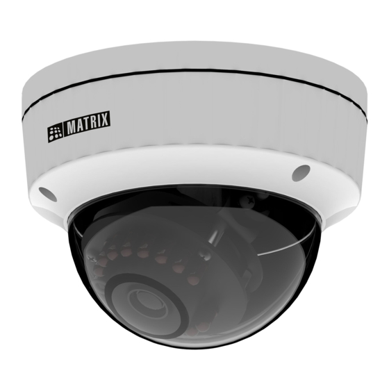
- Page 1 SATATYA Professional Dome IP-Camera The Persistent Vision...
- Page 2 Consignes de sécurité Safety Instructions These instructions are intended to ensure that the user can Ces instructions ont pour but de garantir que l'utilisateur peut Utilisez use the product correctly to avoid danger or property loss. le produit correctement pour éviter tout danger ou perte de propriété. Cautions Précautions •...
-
Page 3: Table Of Contents
Please read this guide first for correct installation and retain it for future reference. The 2. Cable Assembly 5. Enclosure Bottom information in this guide is prevailing at the time of publication. However, Matrix Comsec reserves the right to make changes in product design and specifications without prior 3. Top Glass 6. -
Page 4: What Your Package Contains
What your Package Contains The 5MP Camera variants are listed in below table, • Bullet IP Camera Unit Standard Type of Focal Premium • Wall Mounting Template Lens Length • Wall Mounting Screws with Screw Grip (3 nos.) • Allen Key Fixed •... -
Page 5: Installation
Installation Step 3: Installing Mounting Template • Stick the Mounting Template at the exact location of camera Before you start installation. The location can be ceiling or wall. • Drill three holes through the markings provided on the Mounting Please make sure, •... -
Page 6: Mounting The Camera
Step 4 Taking off the cable Step 5: Mounting the Camera For External Cabling: • Take off the enclosure top by removing 3 screws using screw driver, • Pull the cable out through the cable guide, sideways to the camera, see Figure 4. -
Page 7: Adjusting Camera Angle
Figure 5 Figure 6 Wall/Ceiling Screws Mounting Template Figure 7 Step 6: Adjusting Camera Angle Loosen the screws on both sides of lens to adjust the camera angle, see Figure 6. A. PAN Movement For PAN movement you can move the camera to 45 degrees each side. - Page 8 Figure 9 B. Tilt Movement • For Tilt movement, move the camera from minimum -5 degree to maximum 70 degree, see Figure 8. • If the horizontal view is not aligned i.e. the view is tilted, then you can adjust the view by loosening the screw and adjusting the lens accordingly, see Figure 6.
-
Page 9: Accessing Reset Switch And Sd Card Slot
Accessing Reset Switch & SD Card Slot IP66 Protection Accessory Installation If you forget the IP address or login credentials of camera then the 1. By default your camera contains the LAN connector fitted by IP66 camera can be reset to factory default settings using the reset switch. protection accessory. - Page 10 6. Insert male RJ45 connector into female connector part. Then tighten the middle part by rotating in clockwise direction. IP66 accessory LAN Connector Do not remove the “O” ring from its place. 4. Loosen the tail end of the IP66 accessory by rotating it in anticlockwise direction.
-
Page 11: Powering The Camera
Powering the Camera LED: CLASS1 (Category RS1) Never look at the transmit laser while the power is on. Never look directly at the fiber ports and the fiber cable ends when they are powered on. Audio IN Use of controls or adjustment to the performance or procedure Audio Out other than those specified herein may result in hazardous laser emission. -
Page 12: Network Configuration
System. your PC. Then install the software to configure the IP address. In Internet Explorer you can access the camera with Matrix Steps to get the IP address, ActiveX plugin. In other browsers you need to install •... - Page 13 • Enter the User Name and Password. • By default, you can login with User Name as admin, operator or viewer with the password as admin, operator and viewer respectively. • Click on Login. Ÿ The ActiveX control will get installed on your PC. Ÿ...
-
Page 14: Technical Specification
Ÿ Install the Camera software by clicking on Install. Technical Specification Specification Standard Premium Power Supply Adapter 12V DC (802.3af, Class 2) 12VDC 0.7A; max: 8.5W Power Consumption PoE (36V to 57V)(0.3A to 0.2A); max: 10W Connectors • The home page of the camera will open and the live view Ethernet will be displayed. - Page 15 Motion Detection, Motion Detection, If you are unable to dispose-off the products or unable to locate e-waste View Tamper, View Tamper, recyclers, you may return the products to Matrix Return Material Trip Wire, Trip Wire, Authorization (RMA) department. Zone Intrusion...
- Page 16 MATRIX COMSEC Head Office 394-GIDC, Makarpura, Vadodara - 390010, India Ph: (+91)1800-258-7747 Email: Support@MatrixComSec.com www.matrixvideosurveillance.com...
Need help?
Do you have a question about the SATATYA Professional Series and is the answer not in the manual?
Questions and answers
Is the MIDR50FL28CWS compatible with my Ali-NVR3316P?