Table of Contents
Advertisement
Quick Links
Advertisement
Table of Contents

Subscribe to Our Youtube Channel
Related Manuals for Mercury GO BOLDLY SeaPro 500hp


Summary of Contents for Mercury GO BOLDLY SeaPro 500hp
- Page 1 Operation Maintenance Manual...
- Page 3 Keep this manual with the product for ready reference whenever you are on the water. Thank you for purchasing one of our products. We sincerely hope your boating will be pleasant. Mercury Marine, Fond du Lac, Wisconsin, U.S.A. Name / function: Christopher D. Drees, President, Mercury Marine...
- Page 4 The product you have purchased comes with a Mercury Marine Limited Warranty. The terms of the warranty are set forth in the Warranty Manual, which can be accessed any time on the Mercury Marine website, at http:// www.mercurymarine.com/warranty‑manual. The Warranty Manual contains a...
- Page 5 In addition, certain Mercury Marine products are tested in a controlled and monitored environment, for up to 10 hours of engine run time, in order to verify and make a record of compliance with applicable standards and regulations.
-
Page 7: Table Of Contents
General Information Boater's Responsibilities..................1 Boat Horsepower Capacity................. 1 High‑Speed and High‑Performance Boat Operation.......... 1 Propeller Selection....................2 Outboard Remote Control Models ..............2 Lanyard Stop Switch................... 2 Protecting People in the Water................5 Passenger Safety Message ‑ Pontoon Boats and Deck Boats......5 Wave and Wake Jumping................... - Page 8 Features and Controls Electronic Remote Control (ERC)..............27 Active Trim......................37 Adaptive Speed Control..................44 Engine Synchronization (Multiple Engines)............44 Helm Transfer....................44 Quick Steer....................... 46 Throttle and Shift Operation with Three or Four Engines......... 47 Single‑Lever Mode (Multiple Engines).............. 50 Start/Stop All Engines..................
- Page 9 Maintenance Cleaning Care Recommendations..............70 Use Of Anti‑fouling Bottom Paint Prohibited............. 72 EPA Emissions Regulations................73 Inspection and Maintenance Schedule............. 74 Hood Opening....................76 Hood Removal....................78 Hood Installation....................78 Top Cowl Removal and Installation..............79 Flushing the Cooling System................84 Fuel System......................
- Page 10 Owner Service Assistance Service Assistance..................121 Ordering Literature..................123 Maintenance Log Maintenance Log.................... 125 viii...
-
Page 11: General Information
For additional information, obtain a copy of our Hi‑Performance Boat Operation booklet from your dealer, distributor, or Mercury Marine. -
Page 12: Propeller Selection
Mercury dealer. Outboard Remote Control Models The outboard must be equipped with a Mercury remote control designed for digital throttle and shift. Start‑in‑gear protection is provided by the remote control system. - Page 13 GENERAL INFORMATION The lanyard cord is usually 122–152 cm (4–5 feet) in length when stretched out, with an element on one end made to be inserted into the switch and a clip on the other end for attaching to the operator's PFD or wrist. The lanyard is coiled to make its at‑rest condition as short as possible to minimize the likelihood of lanyard entanglement with nearby objects.
- Page 14 GENERAL INFORMATION While activation of the lanyard stop switch will stop the engine immediately, a boat will continue to coast for some distance depending upon the velocity and degree of any turn at shut down. However, the boat will not complete a full circle.
-
Page 15: Protecting People In The Water
GENERAL INFORMATION Protecting People in the Water WHILE YOU ARE CRUISING It is very difficult for a person standing or floating in the water to take quick action to avoid a boat heading in his/her direction, even at slow speed. 21604 Always slow down and exercise extreme caution any time you are boating in an area where there might be people in the water. - Page 16 GENERAL INFORMATION Persons on the front deck could easily be thrown overboard or persons dangling their feet over the front edge could get their legs caught by a wave and pulled into the water. 26782 WARNING Sitting or standing in an area of the boat not designed for passengers at speeds above idle can cause serious injury or death.
-
Page 17: Wave And Wake Jumping
GENERAL INFORMATION Wave and Wake Jumping Operating recreational boats over waves and wake is a natural part of boating. However, when this activity is done with sufficient speed to force the boat hull partially or completely out of the water, certain hazards arise, particularly when the boat enters the water. - Page 18 GENERAL INFORMATION Reduce speed and proceed with caution whenever you drive a boat in shallow water areas or in areas where you suspect underwater obstacles may exist that could be struck by the outboard or the boat bottom. The most significant action you can take to help reduce injury or impact damage from striking a floating or underwater object is to control the boat speed.
-
Page 19: Exhaust Emissions
Operating a boat or engine with impact damage can result in product damage, serious injury, or death. If the vessel experiences any form of impact, have an authorized Mercury Marine dealer inspect and repair the vessel or power package. Exhaust Emissions... - Page 20 GENERAL INFORMATION Engine exhaust gases contain harmful carbon monoxide. Avoid areas of concentrated engine exhaust gases. When engines are running, keep swimmers away from the boat, and do not sit, lie, or stand on swim platforms or boarding ladders. While underway, do not allow passengers to be positioned immediately behind the boat (platform dragging, teak/body surfing).
-
Page 21: Selecting Accessories For Your Outboard
Some accessories not manufactured or sold by Mercury Marine are not designed to be safely used with your power package and may void warranty. Acquire and read the installation and operation manuals for each selected accessory. - Page 22 (refer to your boat's capacity plate). Know your boat's operating and loading limitations. Know if your boat will float if it is full of water. When in doubt, contact your authorized Mercury Marine dealer or the boat manufacturer. Ensure that everyone in the boat is properly seated.
- Page 23 GENERAL INFORMATION • Do not allow anyone to sit or ride on any part of the boat that was not intended for such use. This includes the backs of seats, gunwales, transom, bow, decks, raised fishing seats, and any rotating fishing seat. Passengers should not sit or ride anywhere that sudden unexpected acceleration, sudden stopping, unexpected loss of boat control, or sudden boat movement could cause a person to be thrown overboard or into the...
-
Page 24: Recording Serial Number
It is important to record this number for future reference. The serial number is located on the outboard, as shown. Model Number XXXXXXXXX Serial Number XXXXXXXX XXXX Mercury Marine Brunswick Corp. Fond du Lac, WI 54935 Assembled in the USA from US and foreign components 71883 Model designation... - Page 25 ***Battery manufacturers may rate and test their batteries to different standards. MCA, CCA, Ah, and reserve capacity (RC) are the ratings recognized by Mercury Marine. Manufacturers that use standards different than these, such as equivalent MCA, do not meet Mercury Marine battery requirements.
-
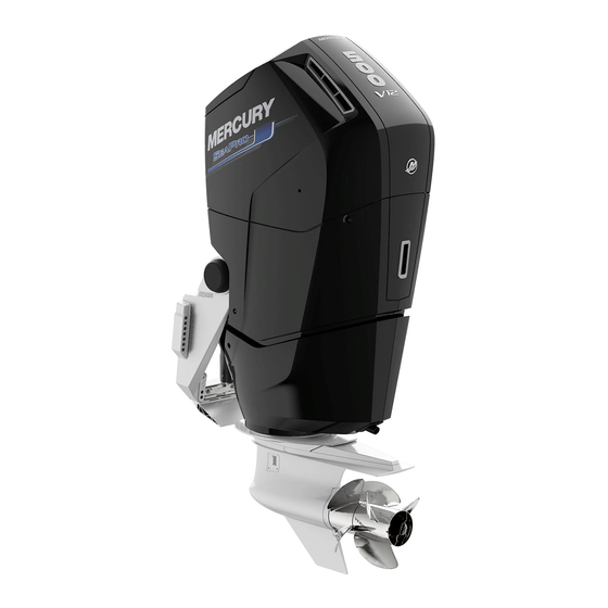
Page 26: Component Identification
GENERAL INFORMATION Component Identification 71884 Hood Top cowl Mid cowl Exhaust relief Lower cowl Cooling water intake holes Manual tilt release (on trim cylinder) Rigging elbow Electronic hood latch release Auxiliary tilt switch... -
Page 27: Transporting And Towing
TRANSPORTING AND TOWING Aquatic Invasive Species (AIS) STOP AQUATIC HITCHHIKERS!™ Be A Good Steward. Clean. Drain. Dry. For additional information, visit StopAquaticHitchhikers.org. 68805 AIS and their spread can detrimentally impact the boating experience and the future of the boating lifestyle. Reducing the spread of AIS has led to significant national efforts to inspect boats moving between water bodies or across state and federal boundaries and could lead to delayed or denied access if AIS are suspected or found on board. -
Page 28: Trailering Boat/Outboard
TRANSPORTING AND TOWING Trailering Boat/Outboard When transporting the boat on a trailer, the outboard should be positioned in the vertical operating position with no additional support required. 71889 If additional ground clearance is required, the outboard should be tilted up as needed and supported with an accessory transom support device. -
Page 29: Fuel And Oil
USA is alcohol (ethanol, methanol, or butanol). GASOLINE CONTAINING ALCOHOL Bu16 Butanol Fuel Blends Fuel blends of up to 16.1% butanol (Bu16) that meet the published Mercury Marine fuel rating requirements are an acceptable substitute for unleaded gasoline. Contact your boat manufacturer for specific recommendations on your boat's fuel system components (fuel tanks, fuel lines, and fittings). -
Page 30: Fuel Additives
Fuel Additives To minimize carbon deposit buildup in the engine, add Mercury or Quicksilver Quickleen Engine and Fuel System Cleaner to the engine's fuel at each tank throughout the boating season. Use the additive as directed on the container. -
Page 31: Oil Life/Maintenance Monitor
FUEL AND OIL • Mercury or Quicksilver NMMA™ FC‑W® certified 10W‑30 Synthetic Blend Marine Engine Oil • Mercury or Quicksilver NMMA™ FC‑W® certified 10W‑30 Marine Engine • NMMA™ FC‑W® certified 10W‑30 Marine Engine Oils IMPORTANT: Nondetergent oils, multiviscosity oils (other than Mercury or Quicksilver NMMA™... - Page 32 FUEL AND OIL A maintenance icon will appear on the VesselView display to notify the user when an oil change is required. Select the 72739 desired engine to proceed to engine‑specific data options. 72741 Maintenance icons—dual-engine shown Maintenance icon ‑ port Maintenance icon ‑...
-
Page 33: Checking And Adding Engine Oil
2. Upon changing the engine oil and completing other scheduled maintenance, reset the oil life/maintenance status. In the VesselView display, navigate to MERCURY ‑> MORE ‑> OIL ‑> OIL LIFE, and press the RESET button for each engine that has been serviced. - Page 34 FUEL AND OIL 5. The oil level check may take up to one minute to complete; one of the following results will appear on the display: • High: The oil level is high. Change the engine oil and filter. Refer to Maintenance ‑...
- Page 35 FUEL AND OIL NOTE: A quick‑reference decal which lists the type of oil to use is located on the underside of the hood. 72637 Decal Oil fill cap Dipstick 3. Remove the dipstick, wipe it clean, and install it fully into the dipstick tube. 4.
- Page 36 FUEL AND OIL 7. Remove the dipstick and observe the oil level. Add oil as necessary to reach the target oil level (1/2 to 2/3 above the bottom of the dipstick crosshatch or ADD mark). 8. Install the dipstick and oil fill cap hand‑tight. 9.
-
Page 37: Features And Controls
Digital Throttle and Shift (DTS) Features. There are several DTS ERCs that can be used with electric steering, depending on the number of engines and the desired features. The following images show the current Mercury ERCs that will function with electric steering. 71712 71715... - Page 38 FEATURES AND CONTROLS 71718 71719 Dual-engine console ERC - Triple-engine console ERC - premier standard 71720 71721 Triple-engine console ERC - Quad-engine console ERC - premier standard 71722 71723 Quad-engine console ERC - Five or six engine console ERC premier The basic styles of ERC are panel mount (single‑engine only), single‑handle console (single‑engine only), and dual‑handle console (two or more engines).
- Page 39 Increases and decreases the brightness settings for the lights on Brightness (+ and –) the ERC and Mercury helm components. Allows the boat operator to increase engine RPM without shifting into THROTTLE ONLY gear.
- Page 40 FEATURES AND CONTROLS Control/LED Function The ACTIVE TRIM button turns the ACTIVE TRIM (if Active Trim feature ON or OFF. Refer equipped) to Active Trim. Changes the selected Active Trim Profile ▲ and ▼ profile. Indicates the currently selected Active Trim profile. Active Trim LEDs (1, NOTE: If the LED indicators are 2, 3, 4, 5)
- Page 41 The light flashes when the engine is in throttle‑only mode. Increases and decreases the brightness settings Brightness (+ and for the lights on the ERC and Mercury helm –) components. Allows boat control to be transferred to a different helm.
- Page 42 FEATURES AND CONTROLS Ref Control/LED Function Raises and lowers the engine/drive for best UP ▲ and DN ▼— efficiency, or for conditions such as shallow water or trailering. Some boats are equipped with trim control separately‑mounted trim controls. Pressing the mechanical lock bar allows the engine to shift.
- Page 43 Increases and decreases the brightness settings Brightness (+ and –) for the lights and display (if equipped) on the ERC and Mercury helm components. Enables the throttle and shift functions of all engines to be controlled by the port lever. Refer to 1 LEVER Single‑Lever Mode.
- Page 44 FEATURES AND CONTROLS Ref Control/LED Function Press to start or stop the indicated engine, as START/STOP equipped: P (port), PC (port center), C (center), SC individual engines (starboard center), S (starboard) Display and display buttons (premier Refer to ERC Supplemental Display for details. ERCs only) Starts or stops all engines.
- Page 45 FEATURES AND CONTROLS ELECTRONIC REMOTE CONTROL (ERC) OPERATION Operation of the shift and throttle is controlled by the movement of the control handle. Push the control handle forward from neutral to the first detent for forward gear. Continue pushing forward to increase speed. Pull the control handle from the forward position to the neutral position to decrease speed and eventually stop.
- Page 46 FEATURES AND CONTROLS Remove the access cover from the front of the ERC to expose the adjustment screws. Using a hex wrench turn the desired screw clockwise to increase tension, or counterclockwise to decrease tension. Install the access cover after the desired tension is achieved.
-
Page 47: Active Trim
58266 Active Trim INTRODUCTION TO ACTIVE TRIM Active Trim is Mercury Marine’s patented GPS‑based automatic trim system. This intuitive, hands‑free system continually adjusts engine or drive trim for changes in operating conditions to improve performance, fuel economy, and ease of operation. It responds to boat maneuvers with precision and delivers a better overall driving experience. - Page 48 Refer to your authorized Mercury dealer for setup and configuration instructions. ACTIVE TRIM ERC CONTROLS IMPORTANT: Authorized Mercury dealers have the ability to disable the Active Trim feature. In this case, the Active Trim buttons and lights on the ERC will not function.
- Page 49 FEATURES AND CONTROLS Use the buttons and lights on the ERC to control the Active Trim feature. 71956 Active Trim controls on the ERC Control/LED Function ACTIVE TRIM Turns the Active Trim feature ON or OFF. button Provides Active Trim status information: •...
- Page 50 FEATURES AND CONTROLS • Active Trim will maintain the last known trim position when operating at speeds in excess of 80 km/h (50 mph). • Operation above 80 km/h (50 mph) may require trim adjustments using the panel mounted or control handle trim position switch. •...
- Page 51 FEATURES AND CONTROLS What Trim Is The trim angle of an outboard or sterndrive is the angle between the boat bottom and the propeller shaft formed by moving the engine or sterndrive closer to the boat transom. This movement is called trimming in or down. Moving the engine or sterndrive further away from the transom is called trimming out or up.
- Page 52 FEATURES AND CONTROLS If the engine or drive is trimmed out too far, the propeller may lose its hold on the water, fast V‑bottom boats may start to walk from side to side (chine walking), steering torque will increase in the opposite direction to that when trimmed in, and getting on plane may be difficult or labored.
- Page 53 FEATURES AND CONTROLS Single Flashing Red 61841 Light (on or off) Interval Fault Condition Description Notes GPS signal has achieved fix, GPS signal Indicates loss of GPS but is dropping out intermittent signal. intermittently. Indicates obstructed GPS signal GPS has not achieved fix since GPS antenna or weak unavailable key on.
-
Page 54: Adaptive Speed Control
FEATURES AND CONTROLS Adaptive Speed Control This outboard package utilizes adaptive speed control which automatically adjusts the engine load (throttle) to maintain engine speed (RPM). For example, when the boat operator steers into a hard turn, which results in increased load on the engine and a loss of RPM, the propulsion control module (PCM) will open the throttle to maintain RPM through the turn, without the need for the operator to increase the remote control throttle handle. - Page 55 FEATURES AND CONTROLS Some fault codes may appear on the Mercury‑approved multifunction display if other control or navigation functions are attempted after the helm transfer procedure is started. To remove the fault codes it may be necessary to cycle the key switch OFF and ON, and then restart the helm transfer procedure.
-
Page 56: Quick Steer
FEATURES AND CONTROLS NOTE: If the helm transfer is not completed in 10 seconds, the request is automatically cancelled and a double beep sounds. Control will remain at the existing active helm. Press the transfer button again to restart helm transfer. 6. -
Page 57: Throttle And Shift Operation With Three Or Four Engines
FEATURES AND CONTROLS • Quick steer limits engine speed. Throttle and Shift Operation with Three or Four Engines TRIPLE-ENGINE THROTTLE AND SHIFT OPERATION Movement of the handles on the remote control allows the boat operator to control the engine throttle speed and gear shift positions of all three engines. The throttle and shift function is dependent on what engines are running. - Page 58 FEATURES AND CONTROLS Turning off one of the outer engines while underway will cause the center engine to go into forced neutral/idle. Operation to the center engine can be restored by moving the control handle of the functioning outer engine back into neutral position and then engaging.
- Page 59 FEATURES AND CONTROLS Port Starboard Port Outer Starboard Inner Inner Control Handle Function Engine Outer Engine Engine Engine Off (ignition Port inner engine throttle key switch Running Running Running and shift = controlled by turned starboard control handle OFF) Starboard inner engine Off (ignition throttle and shift = Running...
-
Page 60: Single-Lever Mode (Multiple Engines)
FEATURES AND CONTROLS If a failure should occur while underway which causes the port outer engines into forced neutral/idle condition, the inner port engine will also be forced to neutral/idle. Operation to the inner engine can be restored by moving the port control handle back into neutral and then engaging. -
Page 61: Throttle-Only Mode
FEATURES AND CONTROLS a. Starboard outer engine ‑ the LED on the starboard outer (S) button will light when the engine starts. b. Port outer engine ‑ the LED on the port outer (P) button will light when the engine starts. c. -
Page 62: Warning System
FEATURES AND CONTROLS NOTE: Throttle‑only mode also affects the joystick, if equipped. The drives will move and the RPM can be increased, but the gear position will remain in neutral. 4. The RPM of the engines can be increased. To disengage throttle‑only mode: 1. - Page 63 SMARTCRAFT PRODUCT A Mercury SmartCraft System instrument package can be purchased for this outboard. A few of the functions the instrument package will display are engine RPM, coolant temperature, oil pressure, water pressure, battery voltage, fuel consumption, and engine operating hours.
-
Page 64: Power Trim And Tilt
FEATURES AND CONTROLS EXHAUST GAS OVER TEMPERATURE When the Engine Guardian system detects the exhaust gas temperature is high (fault code 2124‑20), the warning horn will beep and the engine RPM will be limited. SmartCraft gauges that have the ability display text will alert the operator with a short text, long text, and the action that the operator should follow. - Page 65 FEATURES AND CONTROLS • If the engine is below 2000 RPM and is in the trailer range, advancing the throttle will allow the engine to achieve a maximum RPM of 4250. Engine operation in this capacity (above the normal 2000 limit) should only be used for loading or unloading the boat onto or off the trailer.
- Page 66 FEATURES AND CONTROLS WARNING Operating the boat at high speeds with the outboard trimmed too far under can create excessive bow steer, resulting in the operator losing control of the boat. Install the trim limit pin in a position that prevents excessive trim under and operate the boat in a safe manner.
- Page 67 FEATURES AND CONTROLS MANUAL TILTING If the outboard cannot be tilted using the power trim/tilt switch, the outboard can be manually tilted. To manually tilt the outboard, turn out the manual tilt release valve three turns counterclockwise. Tilt the outboard to the desired position and tighten the manual tilt release valve.
-
Page 68: Transmission And Steerable Gearcase
FEATURES AND CONTROLS 2. Tilt the outboard up. Make sure all the cooling water intake holes stay submerged at all times. • Below 2000 RPM the engine can be trimmed or tilted to any range. Caution is advised when operating the engine past the tilt range. Ensure the water pickups are submerged. -
Page 69: Operation
OPERATION Important Daily Inspection Before Each Use Any outboard mounted on the boat must have the mounting hardware inspected and checked to ensure that the hardware has not become loose. A decal on the transom bracket reminds the owner to check the fasteners securing the outboard to the transom before each use. -
Page 70: Operating In Saltwater Or Polluted Water
(except in freezing temperatures) when not in use. Wash the outboard exterior and flush out the exhaust outlet of the propellers and gearcase with fresh water after each use. Each month, spray Mercury or Quicksilver Corrosion Guard on external metal surfaces. Do not spray on corrosion control anodes as this will reduce the effectiveness of the anodes. -
Page 71: Effects Of Elevation And Weather On Performance
OPERATION Effects of Elevation and Weather on Performance The following conditions lower engine performance and cannot be compensated by the engine fuel or electronic management systems: • Above sea level elevations • High temperature • Low barometric pressure • High humidity These conditions above reduce air density to the engine, which in turn lowers the following: •... -
Page 72: Setting Trim Angle While Running Engine At Idle Speed
OPERATION Setting Trim Angle While Running Engine at Idle Speed The exhaust relief hole on the outboard can become submerged on some boats if the engine is trimmed full in while running at idle speed. This may result in exhaust restriction, rough idle, excessive smoke, and fouled spark plugs. If this condition exists, trim the outboard up until the exhaust relief hole is out of the water. -
Page 73: Ran Out Of Fuel Condition-Priming The Fuel System
7. If the fuel system will not prime within 15 full eight second cranking events, contact an authorized Mercury Marine dealer to prime the fuel system with a fuel rail purge line. Starting the Engine Before starting, read the Prestarting Check List, special operating instructions, Engine Break‑in Procedure, Gear Shifting in this section, and... - Page 74 OPERATION NOTE: The engine electronically monitors engine oil level without user interaction. 2. Verify the cooling water intake is submerged. 71985 3. Set the lanyard stop switch to the RUN position. Refer to General Information ‑ Lanyard Stop Switch. 19791 4.
-
Page 75: Gear Shifting
OPERATION 5. Ignition key starting ‑ Turn the ignition key to the START position and release the key. The electronic starting system will automatically crank the engine for starting. If the engine fails to start, the engine will stop cranking. Turn the key to the START position again until the engine starts. 3485 Gear Shifting IMPORTANT: Observe the following:... -
Page 76: Stopping The Engine
OPERATION • Panel mount and single‑handle electronic remote controls require the operator to press the mechanical lock bar while moving the control handle out of the neutral position. Mechanical lock bar—panel mount ERC Mechanical lock bar— single‑handle ERC 71988 • Always shift the outboard into gear with a quick motion. -
Page 77: Proper Outboard Tilt Positioning During Periods Of Non-Use
OPERATION Reduce engine speed and shift outboard to neutral position. Turn ignition key to OFF position. 3482 Proper Outboard Tilt Positioning During Periods of Non‑Use With the engine turned off, tilt the outboard up to a point where the trailing edge of the anti‑ventilation plate is angled higher than the leading edge. -
Page 78: Steering Failure-Single-Engine Applications
OPERATION Steering Failure—Single‑Engine Applications If the steering system fails on a single‑engine boat, the gearcase can be steered using the following emergency procedure. IMPORTANT: This procedure should only be performed on single‑engine boats. On multiple engine boats, raise the propeller out of the water and use the other engines to return to port. - Page 79 5. Return to port immediately. 6. Turn off the engine and push down on the bypass lever to close the valve. Secure the lever with the pin. Push lever down Install pin 72210 7. Contact an authorized Mercury Marine dealer for service.
-
Page 80: Cleaning Care Recommendations
Record maintenance performed in the Maintenance Log at the back of this book. Save all maintenance work orders and receipts. Selecting Replacement Parts For Your Outboard We recommend using original Mercury Precision or Quicksilver replacement parts and Genuine Lubricants. DO NOT USE CAUSTIC CLEANING CHEMICALS IMPORTANT: Do not use caustic cleaning chemicals on the outboard power package. - Page 81 3. Dry thoroughly with a soft clean cloth. 4. Wax the surface using a nonabrasive automotive polish (polish designed for clear coat finishes). Remove the applied wax by hand using a clean soft cloth. 5. To remove minor scratches, use Mercury Marine Cowl Finishing Compound (92‑859026K 1).
-
Page 82: Use Of Anti-Fouling Bottom Paint Prohibited
Keep water spray out of the air filter/intake and alternator. After washing, allow the powerhead and components to dry. Apply Quicksilver or Mercury Corrosion Guard spray on the external metal surfaces of the powerhead and powerhead components. Do not allow the Corrosion Guard spray to come in contact with the alternator drive belt or belt pulleys. -
Page 83: Epa Emissions Regulations
Due to the fact that the label does not accurately reveal if the paint contains a reactive metal, do not apply any anti‑fouling paint on top of the Mercury factory finish. Warranty: Mercury Marine will not cover corrosion damage on engine or drive parts that have marine anti‑fouling paint applied. -
Page 84: Inspection And Maintenance Schedule
MAINTENANCE EMISSION CERTIFICATION LABEL An emission certification label, showing emission levels and engine specifications directly related to emissions, is placed on the engine at the time of manufacture. EMISSION CONTROL INFORMATION THIS ENGINE CONFORMS TO CALIFORNIA AND U.S. EPA EMISSION REGULATIONS FOR SPARK IGNITION MARINE ENGINES REFER TO OWNERS MANUAL FOR REQUIRED MAINTENANCE, SPECIFICATIONS, AND ADJUSTMENTS IDLE SPEED (in gear):... - Page 85 MAINTENANCE Daily Check Inspect Replace Check that the lanyard stop switch stops the engine. Inspect the fuel system for leaks. Refer to Fuel System. Inspect the tightness on transom. Refer to Inspect Transom Tightness. Check the propellers for damage. Inspect hydraulic hoses for leaks. 200 Hour Maintenance Inspect Replace...
-
Page 86: Hood Opening
MAINTENANCE 1000 Hour Maintenance Inspect Replace Inspect the cooling system water strainer. Refer to Cooling System Water Strainer Inspection. Remove the propellers and grease splines. Refer to Propeller Replacement. Check the power trim fluid level—dealer service. Check valve lash—dealer service (SeaPro models only). Change the engine oil and filter. - Page 87 MAINTENANCE MANUAL HOOD OPENING IMPORTANT: The hood uses a gas shock to hold it in the fully open position. The shock also aids hood opening, resulting in a force that may be unexpected by the operator. Keep your body and all objects clear of the hood while it is opening.
-
Page 88: Hood Removal
MAINTENANCE 3. Install the manual override access plug into the hood opening. Manual override access plug 71962 Hood Removal 1. Open the hood. Refer to Hood Opening. 2. Slide the hood release lock bar to the right to unlock. 3. Push the hood back and lift upward off of the hood bracket. 71952 Slide right Push out... -
Page 89: Top Cowl Removal And Installation
MAINTENANCE 3. Slide the hood release lock bar to the left to lock the hood onto the hood bracket. 71954 Install hood on bracket Hood release tab flush with bracket Slide left 4. Close the hood. Top Cowl Removal and Installation TOP COWL REMOVAL 1. - Page 90 MAINTENANCE 4. Stow the electrical latch connector in the bracket located on the oil dipstick tube. Oil dipstick tube Bracket Electrical latch connector 71938 5. Using an M10 hex socket, and an 18 in. extension, loosen the two fasteners from inside the top cowl. NOTE: The two internal fasteners are self‑contained and will remain with the top cowl after they are loose.
- Page 91 MAINTENANCE NOTE: Two clicks will indicate that the latch hook is released. 71953 Lift point/handle Electrical latch connector Internal fasteners (2)—M10 socket with 18 in. extension required Port side latch hook fastener—clockwise Starboard side latch hook fastener—counterclockwise CAUTION The top cowl is heavy. To avoid personal injury or damage to the cowl, always use a lifting aid device or two people when removing and installing the top cowl.
- Page 92 MAINTENANCE TOP COWL INSTALLATION CAUTION The top cowl is heavy. To avoid personal injury or damage to the cowl, always use a lifting aid device or two people when removing and installing the top cowl. 1. With two people or using a lifting aid device, lower the top cowl over the engine onto the middle cowl.
- Page 93 MAINTENANCE NOTE: Two clicks will indicate that the latch hook is engaged. Port side latch hook fastener— counterclockwise Starboard side latch hook fastener— clockwise Middle cowl 71935 5. Using an M10 hex socket, and an 18 in. extension, tighten the two internal fasteners to the specified torque.
-
Page 94: Flushing The Cooling System
MAINTENANCE 6. Remove the electrical latch connector from the bracket on the oil dipstick tube. Oil dipstick tube Bracket Electrical latch connector 71938 7. Connect the electrical latch connector to the hood latch. Hood latch Electrical latch connector 71878 8. Install the hood. Refer to Hood Installation. Flushing the Cooling System Flush the internal water passages of the outboard with fresh water after each use in salt, polluted, or muddy water. - Page 95 MAINTENANCE 2. Thread a water hose into the flush quick connector (5/8 in. garden hose recommended). Water hose Flush quick connector To water tap 72592 3. Locate the engine flush port on the boat transom and insert the flush quick connector. Flush quick connector Engine flush port on transom 72593...
- Page 96 MAINTENANCE 2. Thread a water hose into the flush quick connector (5/8 in. garden hose recommended). Water hose Flush quick connector To water tap 72592 3. Locate the engine flush port on the boat transom and insert the quick‑connect fitting. Flush quick connector Engine flush port on transom 72593...
-
Page 97: Fuel System
MAINTENANCE 5. Press the start button on the boat‑mounted automatic outboard flushing system, or the remote‑mounted button if equipped. See the user manual that comes with the unit for more details. OUTBOARD FLUSHING SYSTEM START WATER INLET 72594 Start button on automatic outboard flushing system Remote‑mounted start button (if equipped) 6. - Page 98 MAINTENANCE BOAT-MOUNTED FUEL FILTER The boat‑mounted fuel filter can be serviced as a general maintenance item when the water‑in‑fuel alarm is activated. WARNING Fuel is flammable and explosive. Ensure that the key switch is OFF and the lanyard is positioned so that the engine cannot start. Do not smoke or allow sources of spark or open flame in the area while servicing.
- Page 99 MAINTENANCE b. Remove the WIF sensor by turning counterclockwise. Fuel filter WIF sensor Rubber boot 72233 8. Wipe up any spilled fuel. Installation 1. Using a hex wrench, remove the plug from the end of the new fuel filter. 2. Verify that the O‑ring is installed on the water‑in‑fuel (WIF) sensor. Lubricate the O‑ring with clean engine oil.
- Page 100 MAINTENANCE 4. Push the rubber boot over the WIF sensor until the plastic cap within the boot is fully seated over the WIF sensor. Pull the remainder of the boot over the fuel filter. 72236 Rubber boot installed 5. Lightly lubricate the fuel filter O‑ring with clean engine oil. Thread the fuel filter clockwise onto the fuel filter base until the O‑ring makes contact with the base.
-
Page 101: Inspect Transom Tightness
MAINTENANCE FILLING THE FUEL SYSTEM Turn the ignition key switch to the RUN position for approximately six seconds to operate the fuel pumps. Start and operate the engine to purge any remaining air from the fuel system. The engine may run rough while the air is purging through the fuel injectors. -
Page 102: Battery Cables And Clean Power Harness
MAINTENANCE Battery Cables and Clean Power Harness The battery cable connections should be checked often for corrosion or loose retaining hardware. Maintaining this electrical connection helps ensure that the engine operation and accessories functionality remains trouble‑free. The engine starting battery cables and the clean power harness wires must be secured to the engine starting battery with nuts. - Page 103 MAINTENANCE IMPORTANT: An ATC fuse has the fuse element enclosed or sealed inside the plastic housing. This type of fuse must be used for marine applications. Marine applications are exposed to environments that may have the potential to accumulate explosive vapors. ATO fuses have exposed elements and should never be used in marine applications.
-
Page 104: Corrosion Control Anodes
MAINTENANCE Corrosion Control Anodes The outboard has corrosion control anodes at different locations. Anodes help protect the outboard against galvanic corrosion by sacrificing its metal to be slowly eroded instead of the outboard metals. Each anode requires periodic inspection, especially in saltwater, which will accelerate the corrosion. - Page 105 Lock button 72238 NOTE: A powered Mercury fluid transfer pump is recommended, as it is equipped with an appropriate fluid drain hose. If an alternative transfer pump is used, obtain a Mercury oil drain hose to adapt to the pump.
- Page 106 MAINTENANCE Fluid Transfer Pump 8M0180953 Aids in the removal and addition of engine fluids. 72539 Oil Drain Hose 8M0129230 Aids in the removal of engine oil without draining the crankcase. Connect to the crankcase oil pump. 64627 6. Place the fluid transfer pump drain tube into an appropriate container. The container should be large enough to hold more than 15 liters (15.85 US qt).
-
Page 107: Checking Engine Oil Level
MAINTENANCE Oil Filter Wrench 91‑889277 Aids in the removal of the oil filter. 5221 3. Clean the remaining oil from the filter mounting base area. 4. Apply a film of clean oil to the filter gasket. IMPORTANT: Do not use grease on the filter gasket. 5. -
Page 108: Gearcase Lubricant
(chips) may indicate abnormal gear wear and should be checked by an authorized dealer. RECOMMENDED GEARCASE LUBRICATION Mercury or Quicksilver High Performance Gear Lubricant is recommended. If the recommended Mercury or Quicksilver lubricant is not available, SAE 90 API GL‑4 gear oil is a suitable alternative. - Page 109 The lock button on the fluid drain hose will snap into place. NOTE: A powered Mercury fluid transfer pump is recommended, as it is equipped with an appropriate fluid drain hose. If an alternative transfer pump is used, obtain a Mercury fluid drain hose to adapt to the pump.
- Page 110 MAINTENANCE Fluid Drain Hose 8M0129230 Aids in the removal of engine fluids. Connect to a fluid transfer pump. 64627 72281 Gearcase fill/evacuation tube Fluid drain hose lock button 4. Remove the gearcase vent filter or cap from the vent tube. The vent tube is located behind the fill/evacuation tube.
- Page 111 1. Ensure that the engine is trimmed to the vertical operating position. 2. Place an overflow tube on the gearcase vent tube in case of an overfill. NOTE: A Mercury fluid drain hose can be used for this purpose. Fluid Drain Hose 8M0129230 Aids in the removal of engine fluids.
- Page 112 MAINTENANCE DRAINING AND FILLING THE GEARCASE USING GEARCASE SCREWS—METHOD 2 Draining the Gearcase 1. Trim the engine out to approximately 30 degrees. 2. Place a pan below the gearcase to capture the lubricant. 3. Remove the lower gearcase drain screw. Ensure that the gasket comes off with the screw and is not stuck in the housing.
-
Page 113: Transmission Fluid
Transmission Fluid RECOMMENDED TRANSMISSION FLUID Mercury or Quicksilver Automatic Transmission Fluid is recommended. If the recommended Mercury or Quicksilver fluid is not available, use a Dexron III fluid listed in the ZF specification TE‑ML 04D as an alternative. TRANSMISSION FLUID CAPACITY 5.7 L (6.0 US qt) - Page 114 6. If the level is low, add the specified transmission fluid. Refer to Filling the Transmission Fluid. NOTE: If the transmission fluid level is extremely low, contact your local authorized Mercury dealer for assistance. 7. Close the hood. DRAINING THE TRANSMISSION FLUID 1.
- Page 115 (not the vent tube). The lock button on the fluid drain hose will snap into place. NOTE: A powered Mercury fluid transfer pump is recommended, as it is equipped with an appropriate fluid drain hose. If an alternative transfer pump is used, obtain a Mercury fluid drain hose to adapt to the pump.
- Page 116 (not the vent tube). The lock button on the fluid drain hose will snap into place. NOTE: A powered Mercury fluid transfer pump is recommended, as it is equipped with an appropriate fluid drain hose. If an alternative transfer pump is used, obtain a Mercury fluid drain hose to adapt to the pump.
- Page 117 MAINTENANCE Fluid Drain Hose 8M0129230 Aids in the removal of engine fluids. Connect to a fluid transfer pump. 64627 72288 Transmission dipstick Transmission vent filter Fluid drain hose (attached to fluid transfer pump assembly) Lock button Dipstick tube 6. Fill a graduated cylinder with approximately 5.7 L (6.0 US qt) of the specified transmission fluid.
- Page 118 MAINTENANCE 4. Remove the transmission vent filter and store it in a dry location. NOTE: Keep the transmission vent filter dry after it is removed. Replace the transmission vent filter if it gets submerged in any liquid, such as water or oil. 5.
-
Page 119: Cooling System Water Strainer Inspection
MAINTENANCE 10. Close the hood. Cooling System Water Strainer Inspection IMPORTANT: The water strainer is an integral component of the cooling system. It should be inspected every 1000 hours of operation. 1. Remove the top cowl. Refer to Top Cowl Removal and Installation. 2. -
Page 120: Propeller Replacement
MAINTENANCE Description lb‑in. lb‑ft Water strainer screws (2) 88.5 – Propeller Replacement PROPELLER REMOVAL WARNING Rotating propellers can cause serious injury or death. Never operate the boat out of the water with a propeller installed. Before installing or removing a propeller, place the drive unit in neutral and activate the lanyard stop switch to prevent the engine from starting. - Page 121 IMPORTANT: Mercury Marine V12 propellers are matched sets. Do not operate the engine without a front and rear propeller of the same pitch. 1. Apply a liberal amount of Extreme Grease to all splined, threaded, and tapered surfaces on the propeller shaft, thrust hubs, propeller nuts, and propeller hubs.
- Page 122 MAINTENANCE 7. Align the splines of the rear (3‑blade) propeller with the splines on the shaft and slide the propeller into place on the inner shaft. 71705 Large thrust hub Front (4‑blade) propeller Large propeller nut Small thrust hub Rear (3‑blade) propeller Small propeller nut 8.
-
Page 123: Dts Wiring System
Accessory Drive Belt The accessory drive belt is located under the flywheel shroud–intake air induction plenum. The accessory drive belt inspection must be completed by an authorized Mercury dealer at the recommended interval. Refer to Inspection and Maintenance Schedule. Fuses IMPORTANT: An ATC fuse has the fuse element enclosed or sealed inside the plastic housing. - Page 124 MAINTENANCE IMPORTANT: Replace the fuse with a new fuse with the same amp rating. 71997 Hood latch ‑ 15‑amp Cowl trim switch ‑ 2‑amp Spare ‑ 2‑amp Fuel pump ‑ 25‑amp Rig center ‑ 15‑amp Spare ‑ 20‑amp Spare ‑ 15‑amp Spare ‑...
- Page 125 MAINTENANCE NOTE: A fuse identification decal is located on the fuse holder cover. 2. Remove the suspected open fuse and look at the silver band inside the fuse. If the band is broken (open), replace the fuse. IMPORTANT: Replace the fuse with a new fuse with the same amp rating. Spare Fuses on Harness GAUGE PWR EXCITE...
- Page 126 MAINTENANCE 3. Remove the suspected open fuse and look at the silver band inside the fuse. If the band is broken (open), replace the fuse. To remove and replace the fuse: IMPORTANT: Replace the fuse with a new fuse with the same amp rating. a.
-
Page 127: Storage
Corrosion Guard External metal surfaces 92-802878 55 Protecting Internal Engine Components Contact an authorized Mercury Marine dealer to execute the following: IMPORTANT: Refer to the appropriate service manual for spark plug inspection, removal, and replacement procedures. • Remove the high tension spark plug leads and spark plugs. -
Page 128: Engine Fluids
STORAGE • Spray approximately 30 ml (1 fl oz) of Storage Seal Rust Inhibitor into each spark plug hole. Description Where Used Part No. Storage Seal Rust Spark plug holes 92-858081K03 Inhibitor • Actuate key/push button start switch to crank the engine through one start cycle, which will distribute the storage seal throughout the cylinders. -
Page 129: Troubleshooting
TROUBLESHOOTING Starter Motor Will Not Crank the Engine POSSIBLE CAUSES • Lanyard stop switch not in RUN position. • Open clean power harness circuit fuse. Refer to Maintenance section. • Remote control is not shifted to the neutral position. • Shift actuator failure. -
Page 130: Performance Loss
TROUBLESHOOTING a. Engine fuel filter is obstructed. Refer to Maintenance section. b. Fuel tank filter obstructed. c. Stuck antisiphon valve located on permanently built‑in type fuel tanks. d. Fuel line is kinked or pinched. • Fuel system is not primed. •... - Page 131 STOLEN POWER PACKAGE If your power package is stolen, immediately advise the local authorities and Mercury Marine of the model and serial numbers and to whom the recovery is to be reported. This information is maintained in a database at Mercury Marine to aid authorities and dealers in the recovery of stolen power packages.
- Page 132 OWNER SERVICE ASSISTANCE RESOLVING A PROBLEM Satisfaction with your Mercury product is important to your dealer and to us. If you ever have a problem, question or concern about your power package, contact your dealer or any authorized Mercury dealership. If you need additional assistance: 1.
- Page 133 Before ordering literature, have the following information about your power package available: Model Serial Number Horsepower Year UNITED STATES AND CANADA For additional literature for your Mercury Marine power package, contact your nearest Mercury Marine dealer or contact: Mercury Marine Telephone Mail Mercury Marine Attn: Publications Department (920) 929‑5110...
- Page 134 OWNER SERVICE ASSISTANCE Mercury Marine Submit the following Attn: Publications Department order form with payment W6250 Pioneer Road P.O. Box 1939 Fond du Lac, WI 54936-1939 Ship To: (Copy this form and print or type–This is your shipping label) Name...
- Page 135 MAINTENANCE LOG Maintenance Log Record all maintenance performed on your outboard here. Be sure to save all work orders and receipts. Date Maintenance Performed Engine Hours...
Need help?
Do you have a question about the GO BOLDLY SeaPro 500hp and is the answer not in the manual?
Questions and answers