Table of Contents
Advertisement
Quick Links
Advertisement
Table of Contents

Related Manuals for KSB CPKNO


Summary of Contents for KSB CPKNO
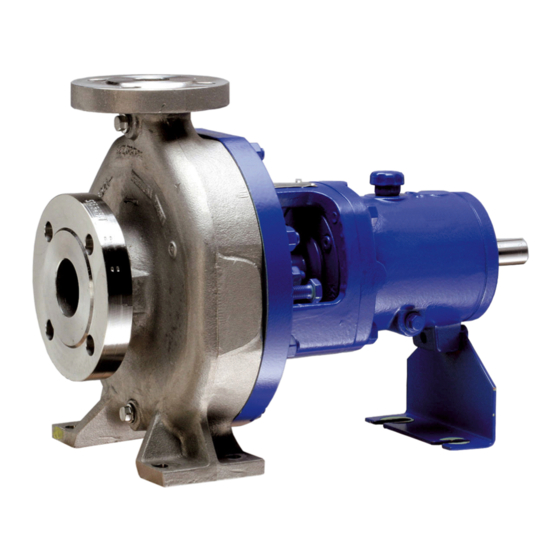
- Page 1 Standardised Chemical Pump CPKNO Installation/Operating Manual...
- Page 2 All rights reserved. The contents provided herein must neither be distributed, copied, reproduced, edited or processed for any other purpose, nor otherwise transmitted, published or made available to a third party without the manufacturer's express written consent. Subject to technical modification without prior notice. © KSB SE & Co. KGaA, Frankenthal 17/08/2021...
-
Page 3: Table Of Contents
Piping ................................ 24 5.4.1 Connecting the piping........................ 24 5.4.2 Permissible forces and moments at the pump nozzles.............. 26 5.4.3 Auxiliary connections......................... 27 Enclosure/insulation ............................ 27 Checking the coupling alignment ......................... 28 Aligning the pump and motor ........................ 29 5.7.1 Motors with adjusting screw...................... 29 CPKNO 3 of 76... - Page 4 7.6.1 Tightening torques .......................... 60 7.6.2 Tightening torques for the impeller nut .................. 61 Spare parts stock............................. 61 7.7.1 Ordering spare parts.......................... 61 7.7.2 Recommended spare parts stock for 2 years' operation to DIN 24296 .......... 62 7.7.3 Interchangeability of pump components.................. 63 CPKNO 4 of 76...
- Page 5 Contents Trouble-shooting.......................... 64 Related Documents .......................... 66 General assembly drawing with list of components .................. 66 EU Declaration of Conformity ...................... 70 Certificate of Decontamination...................... 71 Index .............................. 72 CPKNO 5 of 76...
-
Page 6: Glossary
Pump Machine without drive, additional components or accessories Pump set Complete pump set consisting of pump, drive, additional components and accessories Suction lift line/suction head line The pipeline which is connected to the suction nozzle CPKNO 6 of 76... -
Page 7: General
In the event of damage, immediately contact your nearest KSB service facility to maintain the right to claim under warranty. 1.2 Installation of partly completed machinery To install partly completed machinery supplied by KSB refer to the sub-sections under Servicing/Maintenance. -
Page 8: Key To Safety Symbols/Markings
In conjunction with one of the signal words this symbol indicates a hazard involving electrical voltage and identifies information about protection against electrical voltage. Machine damage In conjunction with the signal word CAUTION this symbol indicates a hazard for the machine and its functions. CPKNO 8 of 76... -
Page 9: Safety
Deficits in knowledge must be rectified by means of training and instruction provided by sufficiently trained specialist personnel. If required, the operator can commission the manufacturer/supplier to train the personnel. Training on the pump (set) must always be supervised by technical specialist personnel. CPKNO 9 of 76... -
Page 10: Consequences And Risks Caused By Non-Compliance With This Manual
▪ Only perform work on the pump set when it has been disconnected from the power supply (de-energised). ▪ The pump (set) must have cooled down to ambient temperature. ▪ Pump pressure must have been released and the pump must have been drained. CPKNO 10 of 76... -
Page 11: Unauthorised Modes Of Operation
They include only a general safety margin for the mechanical seal. For single mechanical seals, the safety margin required for specific operating conditions and mechanical seal designs may be substantially higher. If operating conditions differ CPKNO 11 of 76... -
Page 12: Monitoring Equipment
If the pump is to be operated at a higher temperature, the data sheet is missing or if the pump is part of a pool of pumps, contact KSB for the maximum permissible operating temperature. 2.9.3 Monitoring equipment The pump (set) must only be operated within the limits specified in the data sheet and on the name plate. -
Page 13: Transport/Storage/Disposal
1. On transfer of goods, check each packaging unit for damage. 2. In the event of in-transit damage, assess the exact damage, document it and notify KSB or the supplying dealer and the insurer about the damage in writing immediately. -
Page 14: Storage/Preservation
4. Always complete and enclose a certificate of decontamination when returning the pump. Indicate any safety measures and decontamination measures taken. (ð Section 11, Page 71) NOTE If required, a blank certificate of decontamination can be downloaded from the following web site: www.ksb.com/certificate_of_decontamination CPKNO 14 of 76... -
Page 15: Disposal
Collect greases and other lubricants during dismantling. 2. Separate and sort the pump materials, e.g. by: - Metals - Plastics - Electronic waste - Greases and other lubricants 3. Dispose of materials in accordance with local regulations or in another controlled manner. CPKNO 15 of 76... -
Page 16: Description Of The Pump (Set)
4.2 Product information as per Regulation No. 1907/2006 (REACH) For information as per chemicals Regulation (EC) No. 1907/2006 (REACH), see https:// www.ksb.com/ksb-en/About-KSB/Corporate-responsibility/reach/ 4.3 Designation Example: CPKNO - C1.V F 40-200 Table 5: Key to the designation Code Description CPKN Type series Open impeller C1.V... -
Page 17: Design Details
▪ Standardised mechanical seals to EN 12756, K design Table 6: Seal chamber with different shaft seals (examples) Type of seal Drawing Conical seal chamber (A-type cover) Standardised mechanical seal D00458 Cylindrical seal chamber Standardised mechanical seal D00459 CPKNO 17 of 76... - Page 18 Bearing bracket designation Example: UP03 Table 7: Bearing bracket designation Designation Description Bearing bracket Size code (based on dimensions of seal chamber and shaft end) Bearings used Table 8: Bearing design KSB designation FAG designation SKF designation B-TVP-UA BECBP B.G 8 B-TVP-UA 80 BEC86P Table 9: Standard bearing assembly...
-
Page 19: Design And Function
(8). The shaft runs in rolling element bearings (9 and 10), which are supported by a bearing bracket (5) linked with the pump casing and/or casing cover. Sealing The pump is sealed by a shaft seal (standardised mechanical seal or gland packing). CPKNO 19 of 76... -
Page 20: Noise Characteristics
Surface sound pressure level as per ISO 3744 and DIN EN ISO 20361 ; valid for a pump operating range of Q/ QBEP = 0.8 - 1.1 and non-cavitating operation. If noise levels are to be guaranteed: Add +3 dB for measuring and constructional tolerance. Increase for 60 Hz operation: 3500 rpm +3 dB; 1750 rpm +1 dB; 1160 rpm ±0 dB CPKNO 20 of 76... -
Page 21: Dimensions And Weights
4 Description of the Pump (Set) 4.9 Dimensions and weights For dimensions and weights please refer to the general arrangement drawing/outline drawing of the pump/pump set. CPKNO 21 of 76... -
Page 22: Installation At Site
▷ Install the pump in a horizontal position to ensure self-venting of the pump. DANGER Electrostatic charging due to insufficient potential equalisation Explosion hazard! ▷ Make sure that the connection between pump and baseplate is electrically conductive. CPKNO 22 of 76... -
Page 23: Installation On The Foundation
Perform secondary treatment of the concrete to EN 206. NOTE For low-noise operation contact the manufacturer to check whether the pump set can be installed on anti-vibration mounts. NOTE Expansion joints can be fitted between the pump and the suction line or discharge line. CPKNO 23 of 76... -
Page 24: Installation Without Foundation
Incorrect earthing during welding work at the piping Destruction of rolling element bearings (pitting effect)! ▷ Never earth the electric welding equipment on the pump or baseplate. ▷ Prevent current flowing through the rolling element bearings. CPKNO 24 of 76... - Page 25 Use a filter with laid-in wire mesh (mesh width 0.5 mm, wire diameter 0.25 mm) of corrosion-resistant material. Use a filter with a filter area three times the cross-section of the piping. Conical filters have proved suitable. 5. Connect the pump nozzles to the piping. CPKNO 25 of 76...
-
Page 26: Permissible Forces And Moments At The Pump Nozzles
2200 2750 2100 1400 1450 1100 80-200 3700 2400 2950 3800 1700 1100 2150 1400 2200 2750 2100 1400 1450 1100 80-250 3700 2400 2950 3800 1700 1100 2150 1400 2200 2750 2100 1400 1450 1100 CPKNO 26 of 76... -
Page 27: Auxiliary Connections
Risk of potentially explosive atmosphere due to insufficient venting Explosion hazard! ▷ Make sure the space between the casing cover/discharge cover and the bearing cover is sufficiently vented. ▷ Never close or cover the perforation of the bearing bracket guards (e.g. by insulation). CPKNO 27 of 76... -
Page 28: Checking The Coupling Alignment
ü The coupling guard and its footboard, if any, have been removed. 1. Loosen the support foot and re-tighten it without transmitting any stresses and strains. 2. Place the straight edge axially on both coupling halves. CPKNO 28 of 76... -
Page 29: Aligning The Pump And Motor
4. Re-tighten the hexagon head bolts (1) at the motor and the locknuts (3) at the baseplate. 5. Check proper functioning of coupling/shaft. Check that coupling/shaft can easily be rotated by hand. CPKNO 29 of 76... -
Page 30: Motors Without Adjusting Screw
Risk of injury by rotating shafts! ▷ Always operate the pump set with a coupling guard. If the customer specifically requests not to include a coupling guard in KSB's delivery, then the operator must supply one! ▷ Observe all relevant regulations for selecting a coupling guard. -
Page 31: Electrical Connection
Damage to the pump (set)! ▷ Keep switch-over intervals between star and delta as short as possible. Table 12: Time relay settings for star-delta starting: Motor rating Y time to be set [kW] ≤ 30 < 3 > 30 < 5 CPKNO 31 of 76... -
Page 32: Connecting The Motor
The motor's direction of rotation must match the arrow indicating the direction of rotation on the pump. 3. If the motor is running in the wrong direction of rotation, check the electrical connection of the motor and switchgear, if any. CPKNO 32 of 76... -
Page 33: Commissioning/Start-Up/Shutdown
CAUTION Insufficient quantity of lubricating oil in the reservoir of the constant level oiler Damage to the bearings! ▷ Regularly check the oil level. ▷ Always fill the oil reservoir completely. CPKNO 33 of 76... -
Page 34: Shaft Seal
Double mechanical seal Prior to starting up the pump, apply barrier pressure as specified in the general arrangement drawing. External liquid feed Apply the quantities and pressures specified in the data sheet and the general arrangement drawing. CPKNO 34 of 76... -
Page 35: Priming And Venting The Pump
4. Fit the coupling guard and its footboard, if any. 5. Check the distance between coupling and coupling guard. The coupling guard must not touch the coupling. 6.1.6 Water cooling CAUTION Deposit-forming, aggressive cooling water Damage to the pump! ▷ Observe the cooling water quality. CPKNO 35 of 76... -
Page 36: Cooling Of The Shaft Seal
Explosion hazard! Risk of burns! ▷ Observe the permissible temperature classes. (ð Section 2.9.2, Page 11) CAUTION Lack of heating medium Damage to the pump! ▷ Provide sufficient quantities of a suitable heating medium. Not possible for conical seal chamber (A-type) CPKNO 36 of 76... -
Page 37: Heating Up/Keeping Warm The Pump (Set)
▷ Never operate the pump with the shut-off elements in the suction line and/or discharge line closed. ▷ Only start up the pump set with the discharge-side shut-off element slightly or fully open. GJL-250 to EN 1561 GJS-400-18-LT to EN 1563 CPKNO 37 of 76... -
Page 38: Checking The Shaft Seal
5. Check the coupling alignment and re-align the coupling, if required. 6.1.11 Checking the shaft seal Mechanical seal The mechanical seal only leaks slightly or invisibly (as vapour) during operation. Mechanical seals are maintenance-free. Double mechanical seal CPKNO 38 of 76... - Page 39 Loosen the gland follower and repeat commissioning. Checking the leakage After the leakage has been adjusted, monitor the leakage for about two hours at maximum fluid temperature. Check that enough leakage occurs at the gland packing at minimum fluid pressure. CPKNO 39 of 76...
-
Page 40: Shutdown
DANGER Formation of a potentially explosive atmosphere inside the pump Explosion hazard! ▷ When draining tanks take suitable measures to prevent dry running of the pump (e.g. fill level monitoring). CPKNO 40 of 76... -
Page 41: Ambient Temperature
[Starts/hour] ≤ 12 ≤ 100 > 100 CAUTION Re-starting while motor is still running down Damage to the pump (set)! ▷ Do not re-start the pump set before the pump rotor has come to a standstill. CPKNO 41 of 76... -
Page 42: Fluid Handled
When the pump handles fluids containing abrasive substances, increased wear of the hydraulic system and shaft seal are to be expected. In this case, reduce the commonly recommended inspection intervals. Minimum flow rate Flow rate at best efficiency point Maximum flow rate CPKNO 42 of 76... -
Page 43: Shutdown/Storage/Preservation
▷ As soon as the work is completed, properly re-install and re-activate any safety- relevant devices and protective devices. NOTE If the equipment has been out of service for more than one year, replace all elastomer seals. CPKNO 43 of 76... -
Page 44: Servicing/Maintenance
Fluids handled, consumables and supplies which are hot and/or pose a health hazard Risk of injury! ▷ Observe all relevant laws. ▷ When draining the fluid take appropriate measures to protect persons and the environment. ▷ Decontaminate pumps which handle fluids posing a health hazard. CPKNO 44 of 76... -
Page 45: Servicing/Inspection
NOTE All maintenance work, service work and installation work can be carried out by KSB Service or authorised workshops. For contact details please refer to the enclosed "Addresses" booklet or visit "www.ksb.com/contact" on the Internet. - Page 46 The bearing temperature must not exceed 90 °C (measured on the outside of the bearing bracket). CAUTION Operation outside the permissible bearing temperature Damage to the pump! ▷ The bearing temperature of the pump (set) must never exceed 90 °C (measured on the outside of the bearing bracket). CPKNO 46 of 76...
-
Page 47: Inspection Work
Excessive temperatures as a result of bearings running hot or defective bearing seals Explosion hazard! Fire hazard! Damage to the pump set! ▷ Regularly check the condition of the lubricant. 7.2.3.1 Oil lubrication The rolling element bearings are usually lubricated with mineral oil. CPKNO 47 of 76... - Page 48 ▷ Collect and dispose of any lubricants. ▷ Observe all legal regulations on the disposal of fluids posing a health hazard. At least once a year For ambient temperatures below -10 °C use a different suitable type of lubricating oil. Contact KSB. CPKNO 48 of 76...
- Page 49 4. Re-fill with oil. (ð Section 6.1.2, Page 33) 7.2.3.2 Grease lubrication The bearings are supplied packed with high-quality lithium-soap grease. 7.2.3.2.1 Intervals The bearings are re-lubricated via the lubricating nipples, see the following drawing. Fig. 16: Position of lubricating nipples Lubricating nipple Lubricating nipple CPKNO 49 of 76...
- Page 50 ▷ Adjust the re-lubrication intervals to the grease used. ü The pump has been dismantled for changing the grease. 1. Only half-fill the bearing cavities with grease. 2. Fill the cavities in the bearing cover until they are about 1/3 full. CPKNO 50 of 76...
-
Page 51: Drainage/Cleaning
For any work on the motor, observe the instructions of the relevant motor manufacturer. For dismantling and reassembly refer to the general assembly drawing. (ð Section 9.1, Page 66) In the event of damage you can always contact our service departments. CPKNO 51 of 76... -
Page 52: Preparing The Pump Set
3. Undo hexagon nut 920.01 at the volute casing. 4. Pull the back pull-out unit out of the volute casing. 5. Remove and dispose of joint ring 411.10. 6. Place the back pull-out unit on a clean and level surface. CPKNO 52 of 76... -
Page 53: Removing The Impeller
3. Remove casing cover 161 with O-ring 412.01 and gland packing 461.01. 4. Remove packing rings 461.01 and lantern ring 458.01, if any, from the packing chamber. 5. Pull off guard 680. 6. Pull shaft protecting sleeve 524.01 and thrower 507.01 off shaft 210. CPKNO 53 of 76... -
Page 54: Dismantling The Bearings
7.5 Reassembling the pump set 7.5.1 General information/Safety regulations WARNING Improper lifting/moving of heavy assemblies or components Personal injury and damage to property! ▷ Use suitable transport devices, lifting equipment and lifting tackle to move heavy assemblies or components. CPKNO 54 of 76... -
Page 55: Installing The Bearings
ü The individual parts have been placed in a clean and level assembly area. ü All dismantled parts have been cleaned and checked for wear. ü Any damaged or worn parts have been replaced by original spare parts. ü The sealing surfaces have been cleaned. CPKNO 55 of 76... - Page 56 17. Fit pump-end bearing cover 360.01 with joint ring 400.01; take care not to damage lip seal 421.01. 18. Fit motor-end bearing cover 360.02 with joint ring 400.02; take care not to damage lip seal 421.02. CPKNO 56 of 76...
- Page 57 Table 24: Dimension A for adjusting the impeller clearance Bearing bracket Size Dimension A UP02 25-160 25-200 32-125 32-160 32-200 40-160 40-200 50-160 50-200 UP03 65-160 10,5 65-200 80-160 80-200 100-200 32-250 40-250 40-315 50-250 50-315 65-250 80-250 UP04 65-315 80-315 80-400 UP05 200-315 CPKNO 57 of 76...
-
Page 58: Fitting The Shaft Seal
1. Slide thrower 507.01 (if any) onto shaft 210 from the pump end. 2. Carefully press the stationary ring of mechanical seal 433 with O-ring into casing cover 161. 3. Fit casing cover 161 with the inserted stationary ring of the mechanical seal into lantern 344. CPKNO 58 of 76... - Page 59 7. Fit gland follower 452 and lightly fasten it by hand with the two hexagon nuts 920.02; watch discs 550.01. 8. Fit guard 680. 9. Install complete discharge cover 161 with shaft protecting sleeve 524 in the pump; take care not to damage joint ring 411.11. CPKNO 59 of 76...
-
Page 60: Fitting The Impeller
4. Connect the motor to the power supply (refer to manufacturer's product literature). 7.6 Tightening torques 7.6.1 Tightening torques Use a torque wrench to tighten the bolted connections (902.01/920.01) between the volute casing and the bearing bracket lantern. CPKNO 60 of 76... -
Page 61: Tightening Torques For The Impeller Nut
These values are determined on the basis of a friction coefficient of μ = 0.12. After repeated tightening of the threads and in case of good lubrication the values shall be reduced by 15 to 20 %. CPKNO 61 of 76... -
Page 62: Recommended Spare Parts Stock For 2 Years' Operation To Din 24296
- - - Seal elements for pump casing 150% (set) - - - Coupling and torque- transmitting elements (set) Variants with mechanical seal: Mechanical seal, complete Variants with gland packing: 456.01 Neck bush 461.01 Gland packing (set) 100% CPKNO 62 of 76... -
Page 63: Interchangeability Of Pump Components
Part No. UP02 25-160 25-200 32-125 32-160 32-200 40-160 40-200 50-160 50-200 UP03 32-250 65-160 65-200 40-250 40-315 50-250 50-315 65-250 80-160 80-200 80-250 100-200 UP04 65-315 80-315 80-400 UP05 200-315 Depending on mechanical seal type CPKNO 63 of 76... -
Page 64: Trouble-Shooting
If problems occur that are not described in the following table, consultation with the KSB service is required. A Pump delivers insufficient flow rate B Motor is overloaded... - Page 65 In the case of persistent overloading, turn down impeller. ✘ - Density or viscosity of fluid handled Contact KSB. higher than stated in purchase order - Gland follower over-tightened or cocked Correct. ✘ ✘ ✘ ✘...
-
Page 66: Related Documents
471.01 902.02 463.01 452.01 458.01 902.02 920.02 561.03 456.01 454.01 524.01 433.02 461.01 433.02 561.03 524.01 Fig. 21: a) Version with gland packing, b) Mechanical seal with conical casing cover, c) Mechanical seal with cylindrical casing cover CPKNO 66 of 76... - Page 67 Joint ring 411.10 (and 411.15 for version with mechanical seal) depending on the operating temperature. To be ordered separately in spare parts order. Not fitted on version with conical seal chamber Provided for version with gland packing only CPKNO 67 of 76...
- Page 68 456.01 Neck bush 458.01 458.01 Lantern ring 461.01 461.01 Gland packing 463.01 463.01 Drip plate For bearing brackets UP02 and UP04: socket head cap screw 914.04 Not applicable to grease-lubricated versions Only included for grease-lubricated versions CPKNO 68 of 76...
- Page 69 471.01 471.01 Seal cover 411.15 Joint ring 507.01 507.01 Thrower 561.03 Grooved pin 524.01 524.01 Shaft protecting sleeve 411.32 Joint ring 561.02 561.02 Grooved pin Constant level oiler Drip pan Guard Impeller nut 411.31 Joint ring CPKNO 69 of 76...
-
Page 70: Eu Declaration Of Conformity
10 EU Declaration of Conformity 10 EU Declaration of Conformity Manufacturer: KSB SE & Co. KGaA Johann-Klein-Straße 9 67227 Frankenthal (Germany) The manufacturer herewith declares that the product: CPKN, CPKNO, CPKN-CHs KSB order number: ....................▪ is in conformity with the provisions of the following directives / regulations as amended from time to time: –... -
Page 71: Certificate Of Decontamination
We confirm that the above data and information are correct and complete and that dispatch is effected in accordance with the relevant legal provisions....................................Place, date and signature Address Company stamp Required field CPKNO 71 of 76... -
Page 72: Index
Frequency of starts 41 Partly completed machinery 7 Function 19 Permissible forces and moments at the pump nozzles 26 Piping 25 General assembly drawing 66 Preservation 14, 43 Gland packing 39 Priming and venting 35 Grease lubrication Product description 16 Grease quality 50 Intervals 49 Pure graphite packing 39 CPKNO 72 of 76... - Page 73 Running noises 45, 46 Safety 9 Safety awareness 10 Scope of supply 20 Shaft seal 17 Shutdown 40, 43 Spare part Ordering spare parts 61 Special accessories 20 Start-up 38 Storage 14, 43 Temperature difference 37 Temperature limits 11, 12 Tightening torques 60, 61 Transport 13 Warnings 8 Warranty claims 7 Water cooling 36 CPKNO 73 of 76...
- Page 76 KSB SE & Co. KGaA Johann-Klein-Straße 9 • 67227 Frankenthal (Germany) Tel. +49 6233 86-0 www.ksb.com...
Need help?
Do you have a question about the CPKNO and is the answer not in the manual?
Questions and answers