Table of Contents
Advertisement
Quick Links
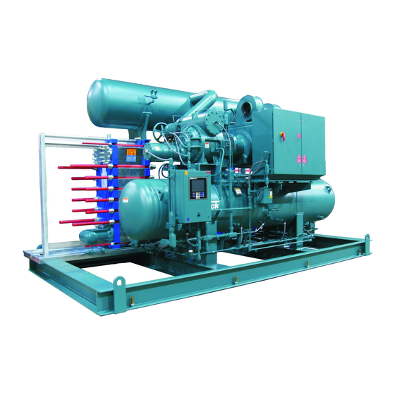
PowerPac
PACKAGED CHILLER UNITS
THIS MANUAL CONTAINS RIGGING, ASSEMBLY, START-UP,
AND MAINTENANCE INSTRUCTIONS. READ THOROUGHLY
BEFORE BEGINNING INSTALLATION. FAILURE TO FOLLOW THESE
INSTRUCTIONS MAY RESULT IN PERSONAL INJURY OR DEATH,
DAMAGE TO THE UNIT, OR IMPROPER OPERATION.
Please check www.johnsoncontrols.com/frick for the latest version of this publication.
Form 170.600-IOM (JUN 2011)
INSTALLATION - OPERATION - MAINTENANCE
File:
SERVICE MANUAL - Section 170
Replaces:
S170-600 IOM (JUN 08)
Dist:
3, 3a, 3b, 3c
™
Advertisement
Table of Contents

Related Manuals for Johnson Controls Frick PowerPac


Summary of Contents for Johnson Controls Frick PowerPac
- Page 1 Form 170.600-IOM (JUN 2011) INSTALLATION - OPERATION - MAINTENANCE File: SERVICE MANUAL - Section 170 Replaces: S170-600 IOM (JUN 08) Dist: 3, 3a, 3b, 3c PowerPac ™ PACKAGED CHILLER UNITS THIS MANUAL CONTAINS RIGGING, ASSEMBLY, START-UP, AND MAINTENANCE INSTRUCTIONS. READ THOROUGHLY BEFORE BEGINNING INSTALLATION.
-
Page 2: Table Of Contents
170.600-IOM (JUN 11) FRICK POWERPAC ® ™ Page 2 INSTALLATION - OPERATION - MAINTENANCE Contents PREFACE......................................3 JOB INSPECTION ...................................3 TRANSIT DAMAGE CLAIMS ................................3 CHILLER AND UNIT IDENTIFICATION ..............................3 PACkAGED AMMONIA CHILLER UNITS ............................4 COMPRESSOR ....................................4 COMPRESSOR CAPACITY CONTROL .............................4 LUBRICATION SYSTEM ..................................4 OIL SEPARATOR/RESERVOIR .................................5 OIL COOLING ....................................5 MOTOR ......................................5... -
Page 3: Preface
All claims must be made by consignee. This is an ICC re- serviceman with the INSTALLATION, OPERATION, and MAIN- quirement. Request immediate inspection by the agent of TEN ANCE procedures as recommended by Johnson Controls- the carrier and be sure the proper claim forms are execut ed. Frick for PowerPac ™... -
Page 4: Packaged Ammonia Chiller Units
170.600-IOM (JUN 11) FRICK POWERPAC ® ™ Page 4 INSTALLATION - OPERATION - MAINTENANCE Condenser Liquid Separator Economizer Evaporator Quantum ™ Compressor PACKAGED AMMONIA CHILLER UNITS a patented method of varying the internal volume ratio to match the system pressure ratio. Either compressor reduces PowerPac™... -
Page 5: Oil Separator/Reservoir
170.600-IOM (JUN 11) FRICK POWERPAC ® ™ Page 5 INSTALLATION - OPERATION - MAINTENANCE OIL SEPARATOR/RESERVOIR SEMIWELDED PLATE EVAPORATOR The evaporator is a plate heat exchanger consisting of a The oil separator is a horizontal, three-stage design with integral sump. The separator is designed and constructed number of cassettes carefully adapted to the actual operating in accordance with ASME Section VIII, Div. -
Page 6: Liquid Refrigerant Separator
170.600-IOM (JUN 11) FRICK POWERPAC ® ™ Page 6 INSTALLATION - OPERATION - MAINTENANCE LIQUID REFRIGERANT SEPARATOR The liquid separator, Figure 3, is of the horizontal type and especially designed for plants with small refrigerant charges and small variations in liquid level. The liquid level can be checked on the liquid level column sight glass, Position 9. -
Page 7: Installation
Figure 4 a trouble-free installation. Use only the certified general The unit may be top heavy. Lifting arrangement drawings from Johnson Controls-Frick to determine the mounting locations and to allow for recom- operators must use extreme care to mended clearances around the unit for ease of operation check the level and stability of the and servicing. -
Page 8: Brine / Water Systems
170.600-IOM (JUN 11) FRICK POWERPAC ® ™ Page 8 INSTALLATION Attention is drawn to the fact that all cooling towers experi- LIFTING LUG CAPACITY, LB/LUG ence a constant loss of water due to evaporation. This makes CABLE ANGLE NOMINAL BEAM impurities remain in the refrigeration system in an ever- MEMBER SIZE VERTICAL... -
Page 9: Holding Charge And Storage
170.600-IOM (JUN 11) FRICK POWERPAC ® ™ Page 9 INSTALLATION HOLDING CHARGE AND STORAGE Each PowerPac chiller is pressure and leak tested at the ™ factory and then thoroughly evacuated and charged with dry nitrogen to ensure the integrity of the unit during shipping and short term storage prior to installation. -
Page 10: Operation
No alignment is required in the field. For replacement motors, the shaft alignment should be checked and tolerances verified with the Johnson Controls- Frick service department. COUPLING DATA TAbLE Coupling Hub... -
Page 11: Compressor Unit Oil
™ 3. Start the compressor as described in the Control Panel drotreated oil as provided by Johnson Controls-Frick. manual. Semisynthetic hydrotreated oil is a synthetic oil with a low 4. Check the compressor for any abnormal noises and make vapor pressure. -
Page 12: Operating Log
170.600-IOM (JUN 11) FRICK POWERPAC ® ™ Page 12 OPERATION The boiling point of a liquid is defined as the temperature at which the vapor pressure is equal to atmospheric pressure. The boiling point of water is 212°F (100°C). If the pressure is lowered, so is the water’s boiling point. -
Page 13: Purging The System
170.600-IOM (JUN 11) FRICK POWERPAC ® ™ Page 13 INSTALLATION PURGING THE SYSTEM Purging of air or other noncondensable gases is required in order to keep high performance of the system and avoid corrosion of the equipment which could endanger the safety of persons and equipment. -
Page 14: Maintenance
LX has a display to read the operating conditions. operation purposes. The pressures and temperatures indicated are not exact. Use only Johnson Controls original spare parts; other parts They can only be used to perform approximate capacity may impair the safety of the compressor/unit. -
Page 15: First Aid In Case Of Ammonia Accidents
170.600-IOM (JUN 11) FRICK POWERPAC ® ™ Page 15 SAFETY First Aid In Case Of Ammonia Accidents SKIN BURNS FROM LIQUID SPLASHES OR (Chemical Formula: Nh – Refrigerant R-717) CONCENTRATED VAPOR 1. Wash immediately with large quantities of water and GENERAL continue for at least 15 minutes. -
Page 16: Ventilating A Refrigeration Plant
170.600-IOM (JUN 11) FRICK POWERPAC ® ™ Page 16 SAFETY When halocarbon vapors come into contact with open flame or hot surfaces over approximately 572°F (300°C) they de- compose to produce poisonous chemicals. These chemicals have a very strong odor warning us of their presence. Oil mist in the ammonia vapor increases this risk significantly as the point of ignition falls below that of the mixture ratio stated. -
Page 17: Forms
170.600-IOM (JUN 11) FRICK POWERPAC ® ™ Page 17 FORMS READ THIS FIRST: COMPRESSOR PRESTART CHECKLIST The following items MUST be checked and completed by the installer prior to the arrival of the Frick Field Service Supervisor. Details on the checklist can be found in this manual. Certain items on this checklist will be reverified by the Frick Field Service Supervisor prior to the actual start-up. - Page 18 FRICK POWERPAC 170.600-IOM (JUN 11) ™ ® FORMS Page 18 Start-up Report Frick Order No: ________________________ Sold To: _______________________________________ Contact Name:__________________________ Date:__________________ End User: ______________________________________ Contact Name:__________________________ Phone:__________________ End User Address: ______________________________________________________________________ Fax No:__________________ City, State, Zip: _________________________________ Start-up Representative _________________ Unit General Information Unit Model # ___________________________________________ Customer Package Identification # _________________________ Compressor Serial # _____________________________________ Separator National Board # ________________________________...
- Page 19 170.600-IOM (JUN 11) FRICK POWERPAC ® ™ Page 19 FORMS Page 2 Unit Serial # _____________________________ Frick Order No: ____________________________ Capacity Control Setpoints Setpoint Regulation Safeties Setpoint Regulation Safeties Load Inhibit ___ Load Inhibit ____ High High Prop. Band ________ ________ Force Unload ________ Prop.
- Page 20 170.600-IOM (JUN 11) FRICK POWERPAC ® ™ Page 20 INSTALLATION - OPERATION - MAINTENANCE Page 3 Unit Serial # _____________________________ Frick Order No: ____________________________ Compressor Motor Setpoints and Information Motor Name Plate Manufacturer ________________ Motor Amps ___________ Maximum Drive Output ___ % Frame Size ______________ Volts ___________ Minimum Drive Output ___ %...
- Page 21 170.600-IOM (JUN 11) FRICK POWERPAC ® ™ Page 21 INSTALLATION - OPERATION - MAINTENANCE Page 4 Unit Serial # ________________ Frick Order No: __________________________________________ P&ID Setpoints Name _________________ __________ _________________ __________ Control ____________ ____________ ____________ ____________ Action ___________ ____________ ____________ ____________ Control Point __________________...
- Page 22 170.600-IOM (JUN 11) FRICK POWERPAC ® ™ Page 22 INSTALLATION - OPERATION - MAINTENANCE VIBRATION DATA SHEET Date: __________________________________________ Sales Order Number: ________________________________ End User: _______________________________________ Installing Contractor: ________________________________ Address: __________________________________________ Service Technician: __________________________________ Equipment ID (As in Microlog): ____________________ Compressor Serial Number: __________________________ Unit Serial Number: _________________________________ National Board Number: _____________________________...
- Page 23 170.600-IOM (JUN 11) FRICK POWERPAC ® ™ Page 23 INSTALLATION - OPERATION - MAINTENANCE Index motor alignment, 10 motorized expansion valve, 12 Ammonia, 15 anchoring, 7 nitrogen charge, 9 noncondensable gases, 13 brine, 8 oil pump, 4 capacity control, 4 oil separator, 5 CO2, 13 operating log, 12...
- Page 24 Form 170-600 IOM (2011-06) JOHNSON CONTROLS Supersedes: S170-600 IOM (2008-06) 100 CV Avenue Subject to change without notice Waynesboro, PA 17268-1206 USA Published in USA • 0112 PDF Phone: 717-762-2121 • FAX: 717-762-8624 www.johnsoncontrols.com/frick © 2012 Johnson Controls Inc. • ALL RIGHTS RESERVED...
Need help?
Do you have a question about the Frick PowerPac and is the answer not in the manual?
Questions and answers