Table of Contents
Advertisement
Quick Links
Advertisement
Table of Contents

Related Manuals for GF NeoFlow DN200


Summary of Contents for GF NeoFlow DN200
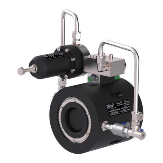
- Page 1 Operating instructions NeoFlow Pressure Reducing Valve DN200 – DN300...
- Page 2 Disclaimer The technical data is not binding. It does not constitute expressly warranted characteristics. And neither guaranteed properties nor guaranteed durability. It is subject to modification. Our General Terms of Sales apply. Observe instruction manual The instruction manual is part of the product and an important element within the safety concept.
-
Page 3: Table Of Contents
CONTENTS PRODUCT DESCRIPTION ....................... 6 Intended Use ..........................6 EC Manufacturer's declaration ....................6 PRESSURE REDUCING VALVE (PRV) CONFIGURATION..............7 1.3.1 METHOD OF OPERATION ...........................7 1.3.2 P&ID ................................7 PRESSURE RATINGS & PERFORMANCE ..................8 FLANGE & SIZING DATA ......................8 NAMEPLATE INFORMATION ...................... - Page 4 WARRANTY. PLEASE CONTACT GF Piping Systems IF YOU ARE IN ANY DOUBT. THE INFORMATION PROVIDED IN THIS DOCUMENT IS ACCURATE AT THE TIME OF PUBLICATION. HOWEVER, IT MAY BE SUBJECT TO CHANGE. THEREFORE, PLEASE CONTACT GF Piping Systems TO ENSURE YOU HAVE THE LATEST VERSION.
- Page 5 Abbreviations EPDM Ethylene Propylene Diene Terpolymer GCR Tech Pressure Controller Halma Pressure Controller P&ID Piping and Instrumentation Diagram Control Space Pressure Pressure Nominal Pressure Reducing Valve Stainless Steel WRAS Water Regulations Advisory Scheme...
-
Page 6: Product Description
Media other than water as well as water containing an amount of disinfectant may only be used in consultation with a contact partner from GF Piping Systems. The use of solid matter in the medium can affect the function of the NeoFlow pressure reducing valve. For this reason, use is only recommended with an upstream strainer. -
Page 7: Pressure Reducing Valve (Prv) Configuration
PRESSURE REDUCING VALVE (PRV) CONFIGURATION 1.3.1 METHOD OF OPERATION Item Description Upstream (inlet) Downstream (outlet) Control block Pilot supply Pilot outlet connection 1.3.2 P&ID Item Description Pressure reducing pilot Strainer Restrictor Isolation ball valve Speed Control Valve IP Valve... -
Page 8: Pressure Ratings & Performance
PRESSURE RATINGS & PERFORMANCE Maximum upstream pressure 16 bar* Downstream pressure range 0.1-16 bar** Minimum Pressure Drop 0.1 bar*** *With medium temperature ≤ 20°C; >20°C on request **Pilot dependent ***Flow rate & size dependent FLANGE & SIZING DATA Nominal Pipe Dimension Flange compatibility Diameter... -
Page 9: Nameplate Information
NAMEPLATE INFORMATION Nameplate Key Data Definition Example Nominal size (DN) (DN)100 bbbbbbbbb Serial number IP2012345 cccc Year of Manufacture 2020 Manufacturer Oxford Flow Manufacturer’s town and country Oxford, UK Regulator type Pilot-operated pressure reducing valve Standard EN1074 Body Material POM-C Nominal size DN DN0200-DN300 Allowable pressure PS... -
Page 10: Bill Of Materials - Pressure Reducing Assembly
BILL OF MATERIALS – PRESSURE REDUCING ASSEMBLY... - Page 11 Item No. Description Quantity (PRV) Main body Oxford Flow PR1 pilot Control block assembly 120 Mesh (125 Micron) Control space circular strainer Control system restrictor block Leengate G1/4 SS Ball Tameson R1/4 to G1/4 Unequal tee Nero R3/8 – R1/4 Reducing nipple Nero R1/4 barrel nipple Vee-Lok R1/4 to 10mm tube straight Vee-Lok R1/4 to 10mm tube elbow...
-
Page 12: Bill Of Materials - Valve Body
BILL OF MATERIALS – VALVE BODY... - Page 13 Item Description Quantity Core Strainer Casing Inlet Shut off seal Nameplate Sticker Isolation valve handle M20 x 1.5 to G1/4 Bulkhead Spring Geann – G3/8 quarter turn ceramic cartridge valve Core seal Primary shaft seal Inlet BS110 Control space seal BS017 Bulkhead seal Socket head bolt –...
-
Page 14: Bill Of Materials - Control Block
BILL OF MATERIALS – CONTROL BLOCK Item No. Description Quantity Control Block 60 Mesh Strainer Control block strainer plug BS119 Strainer... -
Page 15: Bill Of Materials - Pressure Reducing Pilot (Pr1)
1.10 BILL OF MATERIALS – PRESSURE REDUCING PILOT (PR1) Item Description Quantity PR1 Pilot Base Diaphragm Housing Spring Case Diaphragm Support Actuator Upper Spring Guide Diaphragm G1/4 Pilot base plug Pilot setpoint bolt (60mm) PR1 Pilot Nameplate Sticker Pilot Primary Spring Pilot Actuator Spring Pilot Diaphragm Bolt Pilot base seal... -
Page 16: Bill Of Materials - Speed Control
1.11 BILL OF MATERIALS – SPEED CONTROL Item No. Description Quantity Control block mount CAM Restrictor Speed control schematic plate CAM Damper seal Bossard pan head Torx screw 2.2 x 5mm ∅3 x 24mm ISO2338 Parallel dowel pin – A1 SS Eagle Plastic Devices: Dial selector... -
Page 17: Seal Kits
1.11.1 SEAL KITS Valve Size Seal Kits (inc. all O- Rings) DN200 173021008 DN250 173021009 DN300 173021010 1.11.2 PRESSURE SENSE PORTS Logging equipment and pressure gauges can be attached on the upstream, downstream and PCS (Control Space Pressure) control loop ports. Pressure Logging Ports Upstream Downstream... -
Page 18: Pressure Controller Compatibility
1.11.3 PRESSURE CONTROLLER COMPATIBILITY Controller Compatible Comments Replace pilot and control block with i20 system. Addition connection ports provided on request to connect to i20 controller Replace pilot set bolt with an M10 controller bolt 1.12 RECOMMENDED TOOLS AND CONSUMABLES 1.12.1 INSTALLATION/MAINTENANCE TOOLS •... -
Page 19: Installation
2 INSTALLATION Meaning of the Signal Words In this instruction manual, warnings are used, which shall warn the user of death, injuries or material damage. Always read and observe these warnings! DANGER! Imminent danger! Non-observance may result in major injuries or death. ►Measures to avoid the danger. -
Page 20: Transport And Handling
TRANSPORT AND HANDLING Transport via the packaging provided. Do not rest regulator on control system. ►Transport and store the product in its unopened original packing. ►Protect the product from harmful physical influences such as dust, heat, humidity and UV radiation. ►... -
Page 21: Site Selection
SITE SELECTION GF Piping Systems recommend isolation valves (gate or block type) be installed upstream & downstream of the NeoFlow pressure reducing valve to facilitate isolation of the valve for maintenance and repairs. A downstream hydrant and an upstream flow meter are also recommended. - Page 22 Item Description Upstream Isolation Valve Strainer (Recommended) Flow Meter NeoFlow Pressure reducing valve Downstream Hydrant (Recommended) Downstream Isolation Valve Upstream Bypass Isolation Valve Bypass Valve Location Bypass Downstream Hydrant (Recommended) Downstream Bypass Isolation Valve...
-
Page 23: Permitted Valve Orientations
2.2.2 PERMITTED VALVE ORIENTATIONS Horizontal Orientation Vertical Orientation... -
Page 24: Permitted Spatial Dimensions
2.2.3 PERMITTED SPATIAL DIMENSIONS Allow sufficient room around the valve to adjust or disassemble the valve, see table below. VALVE SIZE DN200 520mm 550mm 660mm 380mm DN250 600mm 600mm 800mm 460mm DN300 650mm 680mm 950mm 530mm WARNING All pipework MUST be securely fastened to the ground or other solid object before the installation is commissioned to constrain the valve adequately... -
Page 25: Pilot Spring Options
PILOT SPRING OPTIONS The desired setpoint pressure MUST lie within the pilot spring pressure range. The pilot spring can be identified from the ‘Spring Colour Indication Washer’. It is recommended that the pilot spring is selected so that the maximum setpoint pressure is near to the upper limit of its pressure range, e.g. -
Page 26: Valve Installation
VALVE INSTALLATION CAUTION Damage to the piping system through the effect of forces! Danger of injury and/or material damage due to leaks in the piping system. ► Reduce the forces of thermal expansion of the piping system with the use of suitable fixed points WARNING Danger of material damage due to excessive pressure! If the NeoFlow pressure reducing valve is put into operation without a hydrant excessive outlet pressure P2 on the NeoFlow pressure reducing valve (N) can... - Page 27 a. Fit gaskets and place four stud bolts in the bottom 4 bolt holes. b. Apply grease to the ends of the bolts and add retaining washers and nuts loosely. c. Place valve in the centre of the bolt circle.
- Page 28 d. Insert remaining bolts and tighten four studs in a cross pattern to their designated torques (see section 2.5). Repeat with remaining four studs and re-tighten all eight.
-
Page 29: Valve Bolt Torques
VALVE BOLT TORQUES VALVE SIZE MINIMUM BOLT LENGTH (mm) MAXIMUM TORQUE PER BOLT (Nm) DN200 DN250 DN300 FLANGE ADAPTORS a. Follow steps a-d from section 2.4 within the user specified flange adaptors b. Place flange adaptor/valve assembly into the pipeline and slide the retaining collars onto the pipework, ensuring the flow direction is correct. -
Page 30: Commissioning
3 COMMISSIONING IT IS RECOMMENDED THAT ALL STEPS IN THE COMISSIONING PROCESS ARE FOLLOWED IN SEQUENCE. NEOFLOW EXTERNAL COMPONENTS Item Description Upstream Control-loop Ball Valve Downstream Control-loop Ball Valve Control Space Isolation Valve Speed Control Adjustment Valve... -
Page 31: Setting Speed Control Valve
SETTING SPEED CONTROL VALVE The speed control valve alters the response time and stability of the valve. GF Piping Systems recommend setting the speed control valve to the positions stated in the table below. Recommended Speed Control Size Valve Position... -
Page 32: Initial Pressurising
INITIAL PRESSURISING CAUTION Danger of material damage in the pipeline system. When putting into operation via the main pipeline there is the danger that the initial pressure is too high and the pipeline system is damaged. ► Putting into operation with an outlet hydrant (H) is recommended. ►... - Page 33 Max. Adjustment Spring Downstream sensitivity Colour Pressure (Bar[g]) (Bar/full turn) Black* 0.43 Blue 0.65 ATTENTION Default outlet pressure! At delivery the outlet pressure is set to default. ► The default outlet pressure of the NeoFlow pressure reducing valve with black colour coding of the pilot valve spring is 3 bar.
-
Page 34: Setting Prv Downstream Pressure
d. Slowly open the inlet isolation valve (A) DANGER In new installations or fully drained systems the pipework may shift due to water hammer effect. ► Assume a protected working position ► Ensure personnel are not within valve chambers for initial pressurisation. e. - Page 35 g. Fully open the outlet isolation valve (O). h. Fine tune pilot setpoint to desired downstream pressure, then tighten and secure with the nut.
-
Page 36: Adjusting The Speed Control
CAUTION Danger of displacement of the adjusting Bolt on the pilot valve (AS) during tightening of the locking nut! Potential unintended change of the nominal pressure. ► Always fix the the adjusting screw on the pilot valve (AS) during tightening of the locking nut. ►... -
Page 37: Maintenance
4 MAINTENANCE CAUTION Leaking due to incompatible components! Danger of injury and/or material damage due to exiting liquids due to incompatible components. ► Ensure the compatibility of the specifications of the valve and piping system prior to installation WARNING Maintenance by qualified personnel only! Incorrect handling can damage the NeoFlow pressure reducing valve. -
Page 38: Depressurising Control System
DEPRESSURISING CONTROL SYSTEM To perform live maintenance, the control system must first be isolated and depressurised. To isolate and depressurise the control system: WARNING Water may be ejected at high pressure. Ensure eye protection is worn at all times. Isolate the control space by closing CS (this will hold the current actuator position and hold the setpoint provided the flow rate does not change). -
Page 39: Live Strainer & Control System Flushing
LIVE STRAINER & CONTROL SYSTEM FLUSHING It is recommended to flush the control system of the valve whenever possible to remove debris. This procedure can be performed while the valve is live (i.e. still in service) but it is recommended that the downstream system is isolated (i.e. - Page 40 WARNING Exiting medium! If the sealing plug is removed, the medium may exit uncontrollably from the control block peeling body (1). ► Ensure eye protection is worn at all times ► Assume a protected position. ► Only open ball valves slowly. ►...
-
Page 41: Valve Removal
VALVE REMOVAL DANGER Exiting medium! Ensure suitable isolations are in place upstream and downstream of the NeoFlow installation to prevent release of pressure or continued flow of water. ► Ensure eye protection is worn at all times ► Use safe bolting practices. Undo lower bolts first to relieve any residual pressure and do not remove until satisfied the line is depressurised and drained. -
Page 43: Control System Removal
CONTROL SYSTEM REMOVAL When removing any fitting from the valve always use two spanners on both sides of the fitting to prevent the valve body metal thread inserts becoming loose. a. The pilot control system can be detached and serviced by removing the stainless-steel tubing and four control block M6 bolts as shown. -
Page 44: Control System Servicing
CONTROL SYSTEM SERVICING 4.5.1 CONTROL BLOCK See Section 1.9 for Bill of Materials. a. Remove Strainer with an alley key and flush through with water in accordance with section 4.2. b. Remove the restrictor insert with a flat head screwdriver and inspect for any blockages. c. -
Page 45: Prv Pilot
4.5.2 PRV PILOT Refer to Section 1.10 for Bill of Materials. a. Wind the pilot screw anticlockwise until the loading spring force can no longer be felt. b. Undo the eight bolts and lift the spring housing. - Page 46 c. Lift the diaphragm assembly off the base assembly and visually inspect for wear or damage. d. To replace the diaphragm, undo the top nut on the diaphragm bolt and slide all components off the shaft. Replace the diaphragm and reassemble. e.
-
Page 47: Main Body
MAIN BODY See Section 1.8 for Bill of Materials. a. Firstly, remove the Speed Control Assembly. Note the Control Space Seal below it. b. Rest the valve on the rear face. c. To gain access to the internal O-ring seals loosen the casing bolts around the valve. d. - Page 48 e. Remove the actuator/piston. Inspect the primary shaft O-ring seal for wear or damage. If a metal thread insert becomes loose, remove fully and apply Loctite 5331 thread sealant across the whole thread. Reinsert until the fitting is tight.
- Page 49 CAUTION Lubricate seals and sliding components with an approved lubricant! Correct lubrication of the seals and sliding components is required for the correct functioning of the valve. Other lubricants may attack materials and seals and are not permissible. ► Lubricate seals only with a drinking-water safe lubricant...
-
Page 50: Shut-Off Seal Servicing
4.6.1 SHUT-OFF SEAL SERVICING If the shut-off seal needs servicing, it can be accessed by removing the inlet screws. This can be performed with the control system still on the valve. a. Remove the inlet screws using a Torx-Plus screwdriver head. Remove the inlet strainer and inlet piece to reveal the shut off seal. - Page 51 d. To re-install the shut-off seal, first place it on the inlet component as shown, then place the inlet component back onto the main body casing. e. Retighten inlet screws. Note these are self-tapping screws, tighten until tightening torque noticeably begins to increase.
-
Page 52: Troubleshooting
If the valve is not working as intended, follow NeoFlow Diagnostics Flow Chart A. If the diagnostics flow charts cannot find the root cause or resolve the issue, full valve removal and service is necessary. Contact GF Piping Systems sales team if required. - Page 53 NeoFlow Diagnostic Flow Chart A...
- Page 54 NeoFlow Diagnostic Flow Chart B...
Need help?
Do you have a question about the NeoFlow DN200 and is the answer not in the manual?
Questions and answers