Table of Contents
Advertisement
Available languages
Available languages
Quick Links
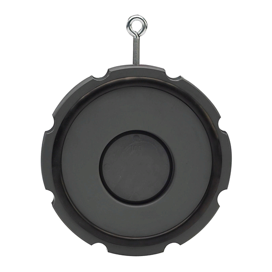
Wafer Check Valve
Type 369
Operating Instructions
700278067 / GFDO 6025 / 05 (12.2021)
© Georg Fischer Piping System Ltd.
CH-8201 Schaffhausen/Schweiz
Printed in Switzerland
Phone +41 52 631 11 11/ info.ps@georgfischer.com
www.gfps.com
3
Congratulations on the purchase and delivery contents
Many thanks that you have decided for the purchase of a Wafer Check
Valve Type 369 from GF Piping Systems.
Please take some time to read carefully this Instruction Manual. It
contains important information and useful tips.
4
Safety Instructions
4.1
Explanations of Warning Symbols
Hazard notices are used in this instruction manual to warn you of
possible injuries or damages to property. Please read and abide by these
warnings at all times!
DANGER!
Imminent acute danger! Failure to comply could result in death or
extremely serious injury.
WARNING!
Possible acute danger! Failure to comply could result in serious injury.
CAUTION!
Dangerous situation! Failure to comply could lead to injury or damage to
property.
4.2
Requirements Placed on the User and Operator's Due Care
It is the responsibility of the piping systems engineer / installer and of
the operator of such systems into which the wafer check valve is built to
warrant that:
► the wafer check valve is only used according to the specifications for
which it has been intended (see next paragraph),
► the piping system is installed by professionals and its functionality
checked regularly,
► only technical correct and functional wafer check valves must be
installed and the security advice is attended,
► only qualified and authorized personnel installs, operates, services
and repairs the wafer check valve,
► instruction of the employees is being held on a regular basis in all the
aspects of work safety and environmental protection – in particular
those to pressure-bearing piping,
► the employees are familiar with the instruction manual and adhere to
the information contained therein.
4.3
Intended Use
These GF wafer check valves type 369 are intended exclusively for
prevention the reflow of media in the allowable pressure and
temperature or for controlling flow in piping systems into which they
have been installed.
The wafer check valves are available with or without reset springs made
of stainless steel V4A or Hastelloy C. The valves are suitable for a
horizontal or vertical installation.
5
Installation in the Piping System
5.1
Note for the Installation
As connecting part we recommend socket flange adaptor or butt fusion
flange adaptor in connection with flanges of PVC-U, PP-V or PP/steel.
WARNING!
► The wafer check valve is approved for PN6.
► No direct installation on pump flange or bend allowed.
CAUTION!
► Torques for fastening has to be taken out of paragraph 5.5.
► The selection of the connection elements must be taken out of the
technical documentation.
► Make sure that only wafer check valves will be installed which
correspond to the pressure class, type of connection, dimension and
materials of the particular application.
► A stabilization zone of at least 5 times nominal diameter (DN) should
be provided before and after the wafer check.
► Carry out a functional test: close the wafer check valve and open it
again.
► Don't install a wafer check valve which has a functional failure.
5.3
Description of Installation
2
3
1
1 = screw and washer
3 = socket flange adaptor / butt fusion flange adaptor
2 = flange
4 = special flange gasket
Before installing
•
Keep enough space between both flanges.
•
Function and tightness testing (reset spring and seals).
•
Fixing of supporting eylet in the provided thread .
While installing
•
Put the wafer check valve in closed position.
•
Attention on the wanted flow direction.
•
Move the wafer check valve with the seals between both flange ends.
•
Realign the pipeline. Make sure that the disc can be fully opened
and that the disk attach on the inner pipe wall.
1
EC Manufacturer's Declaration
The manufacturer GF Piping Systems, 8201 Schaffhausen (Switzerland)
declares that the industrial valves listed below do not fall within the
scope of the Pressure Equipment Directive 2014/68/EU (Art.4, Par.3) due
to the exclusion of their use with hazardous, flammable or gaseous
media and because of their nominal size and pressure rating, and
therefore may not bear the CE marking.
The commissioning of these industrial valves is prohibited until the entire
plant in which the industrial valves are installed has been declared to be
in conformity with the mentioned EC directive.
Product group
Type designation
Harmonized design
standards
Thermoplastic backflow
Wafer check valve
EN ISO 16137
preventers
type 369
Schaffhausen, 22.12.2021
Bastian Lübke
Head of Global R&D
2
List of abbreviation
Abbreviation
Explanation
WCV
Wafer check valve
Type 369
Wafer check valve type 369
DN
Nominal diameter
PN
Pressure rate
d
Diameter
The delivery contents include:
•
Wafer Check Valve Type 369
•
Instruction manual
•
Supporting eyelet
•
Reset spring, depending on the version
CAUTION!
► Wafer check valves are not recommended for media containing solids.
In control operations cavitations have to be avoided.
WARNING!
► The allowable pressure range for all allowable temperatures for every
housing material is illustrated in diagrams in the «Georg Fischer
Planning Fundamentals»(Chapter wafer check valves). This
documentation also contains the «Chemical Resistance List» for the
different type of valve materials.
4.4
Special Hazards
DANGER!
► Pressure strokes have to be avoided, because they can cause
damages on the valve.
The following hazardous situations may occur during dismounting of the
check valve:
DANGER!
► the medium may exit uncontrollably from the pipe or the valve,
whether under pressure or not,
► the medium may flow out of the open pipe,
► the valve may contain residues or remnants of aggressive, hazardous,
flammable or explosive media.
Therefore prior opening the pipe and dismounting the valve, it is
necessary to:
► remove all pressure from the piping system,
► empty the piping system completely,
► rinse the piping system, if aggressive, hazardous, flammable or
explosive media are inside the system,
► to drain the wafer check valve completely when it has been
dismounted. For that, put the valve in vertical position and drain it
completely until it is empty.
4.5
Transport and Storage
The wafer check valve must be handled, transported and stored with
care:
► Transport and store the wafer check valves in its original packaging.
► If the wafer check valve needs to be stored before installation, it must
be protected from harmful influences such as dirt, dust, humidity,
especially heat and UV radiation.
► The connecting ends of the wafer check valve in particular may not be
damaged mechanically or in any other way.
5.2
Important Notes on connecting elements
Components and tightening torques can be determined via the online tool
„Perfect flange connection" at the following link:
https://www.gfps.com/perfectflangeconnection
CAUTION!
• PVC-U
The using of PVC-U pipe PN16 is only possible up to d63. Pay attention on
installation between ISO/ANSI/BS flange adaptors. The WCV DN32 does
not fit together with ANSI/BS flange adaptors. For wafer check valve in
the dimensions DN40 to DN80 and DN200 the next larger size of ANSI/BS
flange adapter has to be used (example: a DN40 valve has to be mounted
between DN50 and DN150 ISO/ANSI/BS flange adaptors).
For dimensions DN100 and DN150, PP-GF flanges must be used.
• PP and PE
To ensure the proper function of the valve in PP and PE piping systems, a
suitable outlet adaptor is required on the outlet side. The outlet adaptor
can be used in the same way as the respective check valve dimension.
Please contact your local GF sales representative for further information.
• PVDF
GF recommends for PVDF piping systems the use of a fusion neck one
size larger than the pipeline or the use of a wafer check valve one size
smaller than the pipe (example: two d110 fusion necks should be used
for the wafer check valve d90).
2
5
3
4
4
5 = wafer check valve type 369
6 = nut and washer
•
Fasten the wafer check valve with flange screws (see chapter 5.5).
After installing
•
Do another functional test.
•
Carry out an leakage test.
5.4
Possible Faults and Problems During Installation
Faults/Problems
Reason
WCV does not fit between
• Wrong dimensioning
the flanges
• Flange ends are too close
to each other
Disc does not open
• Disc larger as the opening
of the chosen adaptor
• Incorrect centring
Disc does not attach on the
•
Incorrect centring
inside of the pipe
•
Wrong dimensioning
Other problems during
• Wrong dimensioning of the
installation
components
5.5
Standard Values for the Screw Fixing
ISO/DIN flange adaptors
WCV dimension
flange dimension
flange dimension
[DN]
[DN]
[d]
DN32
DN32
40
DN40
DN40
50
DN50
DN50
63
DN65
DN65
75
DN80
DN80
90
DN100
DN100
110
DN125
DN125
140
DN150
DN150
160
DN200
DN200
225
DN250
DN250
280
DN300
DN300
315
ANSI/BS flange adaptors , PVC-U wafer check valves only
WCV dimension
flange dimension [Inch] flange dimension
[DN]
[d]
DN40
2"
50
DN50
2 1/2"
63
DN65
3"
75
DN80
4"
90
DN100
4"
110
DN150
6"
160
DN200
8"
225
DN250
10"
280
DN300
12"
315
5.6
Centering and Opening Angle of The Valve
CAUTION!
Make sure that the disk attach on the inner pipe wall. It is not allowed
that the disk attach on the limit stop of the valve.
The geometry of the wafer check valve ensures an optimal positioning
and mounting between ISO/DIN and also of ANSI/BS flange adapters.
The supporting eylets will help during centering the valve.
ANSI/BS flange adaptors
6
Normal Operation and Maintenance
Normally the wafer check valves don't need maintenance. It is enough to
control periodically, if there is a leakage. If you have a leakage in
the flange connections, refasten these acc. to the table in chapter 5.5 or if
it is necessary replace the flange gaskets.
7
Pressure Test and Commissioning
CAUTION!
► For pressure testing of the wafer check valve use the same
instructions as for the piping system.
8
Help in Case of Failures
In case of failures please consider paragraph 4.1 to 4.5. If there is a
leakage in the pipe or to the outside, dismount the wafer check valves
and replace defect gaskets. Orders for spare parts for the waver check
valve should include a detailed specification, i.e. details given on the type
plate. Only the prescribed original spare parts from GF may be used.
Kind of failure
Measures
Leakage on the outside of the
Connection retightening
6
flange adaptor
Leakage in the pass
Demounting of the valve and replace the
disc and sealing. Order spare parts with the
description from the type label
Other function failures
Displace the sealings
Order spare parts with the description from
the type label
Piping strengths, especially these caused by thermal expANSI/BSon,
could be the reason for the malfunction. The support of the piping should
be improved.
If there is a indication after dismounting, that the materials of the body,
the disc or the sealings are not resistant enough, choose a better suited
material from the chemical resistance list, which you will find in our
planning fundamentals.
9
Additional Information
The above mentioned Planning Fundamentals may be obtained from the
GF sales company responsible for your country or from the internet at:
www.gfps.com
The technical data are not binding.
They are not expressly warranted characteristics of the goods and are
subject to change.
Please consult our General Conditions of Supply.
Effect
Solution
Installation not possible
• Selection of the correct dimension on base of
the technical documentation
• Press apart flanges with spreader
No flow possible after
• Selection of the correct dimension on base of
installation
the technical documentation
• Demounting and chamfer of the pipe
• Correct centring
Disc could break
• Correct centring
• Selection of the correct dimension on base of
the technical documentation
Installation not possible
• Selection of the correct dimension on base of
the technical documentation
quantity of screws
screw dimension
torque
[ISO]
[Nm]
4
M16 x 85 mm
15
4
M16 x 85 mm
15
4
M16 x 95 mm
20
4
M16 x 100 mm
25
8
M16 x 110 mm
25
8
M16 x 130 mm
30
8
M16 x 130 mm
35
8
M20 x 180 mm
40
8
M20 x 180 mm
50
12
M20 x 180 mm
55
12
M20 x 180 mm
60
quantity of screws
screw dimension
torque
[ANSI/BS]
[Nm]
4
UNC5/8" x 3 1/2"
20
4
UNC5/8" x 4"
25
4
UNC5/8" x 4"
25
8
UNC5/8" x 4 1/2"
30
8
UNC5/8" x 4 1/2"
30
8
UNC3/4" x 5
40
8
UNC3/4" x 6"
50
12
UNC7/8" x 6 1/2"
55
12
UNC7/8" x 7"
60
Wafer check valve PVC-U
•
Centring on ISO/DIN adaptors over the cut-out
•
Centring on ANSI/BS over the external diameter of the valve
Wafer check valves PP and PVDF
•
Centring over the external diameter of the valve
Cut-out
External diameter
ISO/DIN flange adaptors
WARNING!
► Check all valves if they are in the required open or closed position.
► Fill the piping system and bleed it completely.
► Pressure may not exceed the value of 1.5 x PN.
► During the pressure test the valves and connections should be
checked for leackages.
CAUTION!
Maximum permissible test pressure!
For the pressure test of valves in open position, the same instructions
apply as for the piping system (max. 1.5 x PN, and max. PN + 5 bar), but
the test pressure in closed valve position must not exceed max. 1.1 x PN.
► For detailed information, see the Georg Fischer Planning Fundamen-
tals.
► After successful pressure test: Remove test medium.
► Record the results.
Handling of sealings
CAUTION!
► All sealings (material e.g. EPDM, FKM) are of organic materials and
react to environment influences. They must be stored in their original
packing if possible in a cool,
dry and dark place. The sealings have to be assayed on possible
ageing damages as fissures and hardenings before installing.
► Damaged sealings and spare parts must not come into operation.
Choice of the lubricant
CAUTION!
► The use of inadequate lubricants can affect the material of the wafer
check valve or of the sealings. Lubricants on the base of mineral oil or
of Vaseline (petrolatum) must not
be used at all. For clean silicone-free wafer check valves we refer to
the special manufacturer's information.
► All sealings need to be lubricated with lubricants on the base of
silicone or polycole. Other lubricants are not allowed!
torque
[lbf in]
133
133
177
221
221
266
310
354
442
487
531
torque
[lbf in]
177
221
221
266
266
354
442
487
531
Advertisement
Table of Contents

Subscribe to Our Youtube Channel
Related Manuals for GF 369


Summary of Contents for GF 369
- Page 1 Only the prescribed original spare parts from GF may be used. packing if possible in a cool, GF recommends for PVDF piping systems the use of a fusion neck one dry and dark place. The sealings have to be assayed on possible size larger than the pipeline or the use of a wafer check valve one size ageing damages as fissures and hardenings before installing.
- Page 2 Gratulation zum Kauf und Lieferumfang DN300 DN300 M20 x 180 mm Vielen Dank, dass Sie sich für den Kauf einer Rückschlagklappe Typ 369 Im Lieferumfang sind enthalten: von GF Piping Systems entschieden haben. ANSI/BS Anschlusselemente, nur für PVC-U Rückschlagklappen •...
Need help?
Do you have a question about the 369 and is the answer not in the manual?
Questions and answers