Table of Contents
Advertisement
Available languages
Available languages
Advertisement
Table of Contents

Related Manuals for GF DSR 500-1


Summary of Contents for GF DSR 500-1
- Page 1 GF Piping Systems Betriebsanleitung Operating Instructions Manuel d’utilisation Rückmeldemodul 4-20mA & Endschalter zu DSR 500-1/-2/-3 Feedback Modul 4-20mA & Limit Switch for DSR 500-1/-2/-3 Modul Recopie 4-20mA & Unit.Contact pour DSR 500-1/-2/-3...
-
Page 2: Table Of Contents
Inhalt/Content/Sommaire Betriebsanleitung (deutsch) ..................3 Technische Daten ........................3 Aufbau und Funktion ......................3 Montage ........................... 4 Grenzsignalgeber ........................5 Störmeldung ..........................6 Fehlermeldungen / Problembehandlung ................7 Operating Instructions (English) .............. 8 Technical data ......................... 8 Design and function ........................ 8 Installation .......................... -
Page 3: Betriebsanleitung (Deutsch)
1 Betriebsanleitung (deutsch) 1.1 Technische Daten Versorgungsspannung 24V DC (±10%) Ausgangssignal 4 - 20 mA Maximal zulässige Bürde < 700 Ohm Temperaturbereich -20 . . .+75°C Schaltleistung der Grenzsignalgeber 24V AC/DC , 70mA Schalthysterese ca. 2,5% Das Rückmeldemodul RM-2 kann bei allen Stellungsreglern Typ 8049 in 4-Leiter Ausführung ab Version V5 verwendet werden. -
Page 4: Montage
1.3 Montage Blindstopfen an der Rückseite des Stellungsreglers entfernen. Kabelverschraubung M12x1,5 in den Stellungsregler einschrauben. Rückmeldemodul wie dargestellt auf den Steckplatz (EXTENSION) aufsetzen und festdrücken. Wird das Rückmeldemodul falsch aufgesteckt, so kann dies zu dessen Beschädigung und zur Beschädigung des Stellungsreglers führen. Rückmeldemodul nach folgendem Schaltplan anschließen. -
Page 5: Grenzsignalgeber
Der elektrische Anschluss darf nur durch qualifiziertes Personal erfolgen. Beachten Sie unbedingt bei Montage, Inbetriebnahme und Betrieb der Geräte die entsprechenden nationalen Sicherheitsvorschriften (z. B. VDE 0100). Alle Arbeiten dürfen nur im spannungslosen Zustand erfolgen. Bei Nichtbeachten der entsprechenden Vorschriften können schwere Körperverletzungen und/oder Sachschäden auftreten. -
Page 6: Störmeldung
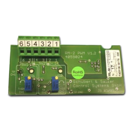
1.4.2 Justage über Vergleichsspannung Auf dem Rückmeldemodul befinden sich drei Testpunkte, über die eine Vergleichsspannung abgegriffen werden kann. Die Vergleichsspannung liegt zwischen 0,1V und 3,2V, was 0% Comp bis 100% Hub entspricht. 5 4 3 2 1 T P (C H 1 ) R M -2 C H 2 C H 1... -
Page 7: Fehlermeldungen / Problembehandlung
Fehlermeldungen / Problembehandlung Fehler / Symptom Mögliche Ursache(n) Vorgehensweise Es liegt keine Spannungsversorgung Rückmeldemodul Versorgungsspannung an. anschließen und einschalten. liefert kein Signal. Versorgungsspannung ist Schaltung nach Schaltplan verpolt. überprüfen. Polung der Versorgungsspannung drehen. Modul hat keine Verbindung ... -
Page 8: Operating Instructions (English)
2 Operating Instructions (English) 2.1 Technical data Supply voltage 24V DC (±10%) Output signal 4 - 20 mA Max. permissible load < 700 Ohm Temperature range -20 . . .+75°C Switching capacity of limit signal transmitter 24V AC/DC , 70mA Switching hysteresis approx. -
Page 9: Installation
2.3 Installation Remove the blanking plug on the rear side of the positioner. Screw the M12x1.5 wiring gland into the positioner. Place the feedback module in the plug-in position (EXTENSION) as shown and push it in. If the feedback module is pushed in incorrectly, damage may occur to the module and the positioner. -
Page 10: Limit Signal Transmitters
The electrical connection must only be performed by qualified personnel. It is imperative that the relevant national safety regulations (e.g. VDE 0100) are observed during installation, commissioning and operation of the device. Ensure that the devices are disconnected from power before performing any work. -
Page 11: Malfunction Message
2.4.2 Calibration by reference voltage The feedback module provides a reference voltage of U at three testing points. The reference voltage has a range of 0.1V to 3.2V, which corresponds to 0% and 100% of the stroke. 5 4 3 2 1 T P (C H 1 ) R M -2 C H 2... -
Page 12: Fault Messages / Troubleshooting
Fault messages / Troubleshooting Fault / Symptom Possible cause(s) Action No supply voltage. Connect power supply and No signal from switch it on. Polarity of supply voltage feedback module Check circuits using the is reversed. wiring diagram. ... -
Page 13: Instructions De Mise En Service (Français)
3 Instructions de mise en service (français) 3.1 Caractéristiques techniques Tension d'alimentation 24V CC (±10%) Signal de sortie 4 - 20 mA Résistance ohmique apparente adm. < 700 ohms Température -20 . . .+75°C Puissance de coupure du transmetteur 24V CA/CC , 70mA Hystérésis de commutation env. -
Page 14: Montage
3.3 Montage Retirer le bouchon situé à l’arrière du positionneur. Visser le presse-étoupe M12x1,5 dans le positionneur. Poser le module de recopie sur l’emplacement (EXTENSION) indiqué sur la photo et appuyer. Un mauvais raccordement du module de réponse peut l’endommager ou endommager le positionneur. -
Page 15: Transmetteurs De Fin De Course
Le raccordement électrique doit impérativement être confié à un personnel qualifié. Les prescriptions de sécurité nationales (par ex. VDE 0100) doivent également être respectées pour le montage, la mise en service et l’exploitation des appareils. Tous les travaux doivent être effectués hors tension. -
Page 16: Signal D'erreur
3.4.2 Réglage par le biais de la tension de référence Le module de recopie comporte trois points de test permettant de mesurer une tension de référence U . La tension de référence est comprise entre 0,1V et 3,2V, ce qui correspond à Réf 0% et 100% de la course. -
Page 17: Messages D'erreur / Traitement Des Erreurs
Messages d’erreur / traitement des erreurs Erreur / Symptôme Cause possible Procédure Absence de tension Raccorder et activer la d’alimentation. tension d’alimentation. Le module de recopie ne La tension d’alimentation Vérifier le montage sur le fournit aucun signal. a été... - Page 18 Notizen / Notes...
- Page 19 Notizen / Notes...
- Page 20 GF Piping Systems 700.278.078 GFDO_6463_1_2_4 GF Piping Systems Ltd CH-8201 Schaffhausen 2016...
Need help?
Do you have a question about the DSR 500-1 and is the answer not in the manual?
Questions and answers