Advertisement
Quick Links
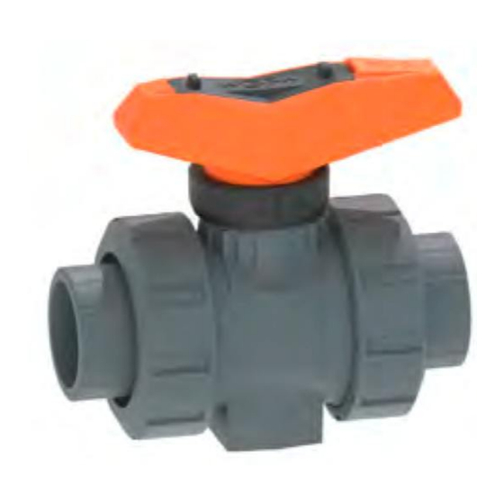
Ball Valve
Type 546 Pro, manual
Instruction Manual
700278101 Ball Valve Type 546 Pro, manual
MA_00015 / DE EN FR ES / 08 (01.2022)
© Georg Fischer Piping Systems Ltd
CH-8201 Schaffhausen/Switzerland
+41 52 631 30 26 / info.ps@georgfischer.com
www.gfps.com
1. Intended Use
The Type 546 Pro Ball Valve will be installed into a piping system
and is intended exclusively for shutting off, passing through
or regulating the flow of approved media within the approved
pressure and temperature limits.
The maximum service life is 25 years.
2. Regarding this Document
2.1 Related Documents
• GF Planning Fundamentals Industry
This document can be obtained from the GF Piping Systems repre-
sentation or at www.gfps.com.
2.2 Abbreviations
PN
Nominal pressure
DN
Dimension
2.3 Safety Instructions and Warnings
Warnings that warn the user of death, injuries or material damage
are used in this instruction manual. Always read and observe these
warnings!
DANGER!
Imminent danger!
Non-observance may result in major injuries or death.
WARNING!
Possible danger!
Non-observance may result in major injuries.
CAUTION!
Dangerous situation!
Non-observance may result in minor injuries.
ATTENTION!
Dangerous situation!
Non-observance may result in material losses.
3. Safety and Responsibility
The safety instructions for the ball valve are usually the same as
for the piping system they are installed in.
►Products may only be used for its intended purpose, see Intended
Use.
►Never use a damaged or defective product. Immediately sort out
damaged or defective products.
►Make sure that the piping system has been installed professio-
nally and serviced regularly.
►Products and equipment shall only be installed by persons who
have the required training, knowledge or experience.
►Regularly train personnel in all relevant questions regarding
locally applicable regulations related to safety at work and envi-
ronmental protection, especially for pressurised pipes.
4. Transport and Storage
►Transport and/or store product in unopened original packaging.
►Protect product from dust, dirt, dampness as well as thermal and
UV radiation.
►Make sure that the product has not been damaged either by
mechanical or thermal influences.
►Store product in open lever position (delivery condition).
►Check product for other damage prior to the installation.
5. Design
14
13
12
10
11
9
2
3
15
6
7
8
7
6
5
4
3
2
1
Pos.
Description
Pos.
Description
1
Union nut
9
Stem
2
Connecting part
10
Stem seals
3
Union seal
11
Body
4
Union bush
12
Locking ring
5
Body seal
13
Lever (lockable)
6
Backing seal
14
Lever clip
7
Ball seat
15
Threaded insert
8
Ball
6. Installation
►Remove the product from its original packaging immediately
before installation.
►Make a function test: close the ball valve by hand and open it
again. Ball valves which do not function properly must not be
►Install the ball valve always into the system in the opened
position.
►Make sure that pressure rating, type of connection and dimensi-
ons correspond to the operating conditions.
►Make sure that the ball valve is aligned with the pipe so that the
valve is kept free of mechanical stress.
►Install ball valve, see steps a – d.
►Adhere specific jointing instructions for solvent cementing, fusi-
on and screw connection methods, see operating manuals of the
fusion machines or the cementing instructions of the adhesive
manufacturer.
►Join the connecting parts with the pipe ends according to materi-
als and types (fusion, cementing, screwing, flanges).
►For the tightening torque of the flange screws and other useful
information, see GF Planning Fundamentals.
WARNING!
Damage to property when using the ball valve as end of line!
If the ball valve is operated without a union nut and connecting part
on one of the outlets, the ball valve may be damaged.
►Operate the ball valve only with connecting parts and union nuts
on all outlets.
WARNING!
The installation dimensions, connections and union nuts of the
ball valve are product specific!
Use of components and installation dimensions other than those
prescribed for this type can cause damage to the piping system.
►Compare the installation dimensions and specifications in the
technical documentation with those of the components at hand.
a - d: Installation
a
b
n - v: Assembly / Montering
n
o
p
Our General Terms of Sale apply.
Observe instruction manual
The instruction manual is part of the product and an important compo-
nent of the safety concept.
• Read and observe the instruction manual.
• Always keep the instruction manual with the product.
• Pass the instruction manual to subsequent users of the product.
EC declaration of conformity
The manufacturer, Georg Fischer Piping Systems Ltd, CH-8201 Schaff-
hausen (Switzerland) declares, in accordance with the harmonized DIN
EN ISO 16135 that the Type 546 Pro ball valves are pressure-bearing
components in the sense of the EC Directive 2014/68/EU concerning
pressure equipment and that they meet the requirements pertaining to
valves as stated in this directive.
The CE-marking on the valve compliance with this Directive (according
to the Directive on pressure equipment, only valves larger than DN25
can be labeled with CE). Operation of these ball valves is prohibited
until conformity of the entire system into which the ball valves have
been installed is established according to one of the above mentioned
EC-Directives.
Modifications to the ball valves which have an effect on the given
technical specifications and the intended use render this declaration of
conformity null and void. Additional information is contained in the „GF
Planning Fundamentals".
Schaffhausen, 06.01.2022
Bastian Lübke
Head of Global R&D
WARNING!
Material damage due to excessive tightening!
Material damage of the union nuts or the thread due to tools, such
as pliers or if they are tightened too strong.
►Thighten the union nuts only handtight without the use of addi-
tional tools.
WARNING!
Material damage due to nonobservance of the insertion depth!
The pressure load of a damaged housing can cause breakage.
► When using the integrated fastening in the foot of the ball valve,
always observe the requirements regarding the maximum inser-
tion depth of the screws.
Maximum insertion depth of the screws into the ball valve
DN
10/15 20/25
32/40
Screw
M6
M6
M8
Insertion depth H (mm)
12
12
15
ATTENTION!
Forces due to thermal expansion!
In piping systems with temperature fluctuations, bending and
longitudinal forces can occur if heat expansion is hindered.
In order as not to impair the functioning of the valve:
►Forces must be absorbed by implementing suitable fixed points
in front of or behind the valve.
Use mounting plate for front fastening. Forces which can occur
during valve operation are absorbed (e.g. initial break-away
torque). The operating forces are thus prevented from being
transferred over to the piping system.
7. Commissioning
►Check whether all valves are in the required open or closed
position.
►Fill and completely vent piping systems.
►The component with the lowest PN determines the maximum
allowed test pressure in the performance section.
►During the pressure test, check valves and connections for leaks.
CAUTION!
Maximum permissible test pressure!
For the pressure test of ball valves in the open position, the same
instructions apply as for the pipes (max. 1.5 x PN, and max. PN + 5
bar), but the test pressure in the closed position must not exceed
max. 1.1 x PN.
►For detailed information, please see the GF Planning Fundamen-
tals.
►After the leak test: remove the test medium.
►Record results.
8. Disassembly
WARNING!
Risk of injury due to uncontrolled evasion of the medium!
If the pressure was not relieved completely, the medium can evade
uncontrolled. Depending on the type of medium, risk of injury may
exist.
►Completely relieve pressure in the pipes prior to dismounting.
►Completely empty and rinse pipe prior to dismounting in connec-
tion with harmful, flammable, or explosive media. Pay attention
to potential residues.
►Provide for safe collection of the medium by implementing ap-
propriate actions (e.g. connection of a collection container).
1
►Partially open the dismounted ball valve (45° position) and let
drain in vertical position.
►After dismounting, the ball valve should be stored in a safe place.
When the ball valve has been removed from the pipe by loosening
the union nut and preparations have been made for drainage,
disassemble the valve by following steps e – m.
►The locking ring must be in the open position (top).
9. Maintenance
Ball valves require no maintenance under normal operating condi-
tions. However, following measures must be noted:
►Periodic inspection to make sure that no medium is leaking is
sufficient.
►Make a function test for ball valves which are kept permanently
in the same position 1–2 x a year to check serviceability.
►Recommendation when using aggressive media: periodically
(depending on the aggressiveness of the medium as well as the
utilization of the goods) remove the ball valve from the line by
loosening the union nuts and check the inside for damage.
For frequent control operations – valve automation, or due to
chemical attack on the sealing material – it may become necessary
to replace parts inside the valve. For this purpose, the valve must
be removed from the piping system. The sealing elements, as well
as the ball, stem and union bush can be replaced, see spare parts
list of GF Piping Systems.
CAUTION!
Material damage and/or risk of injury!
Only original Georg Fischer spare parts designed specifically for
this valve may be used for replacement purposes.
►Note all the details given on the type plate when ordering spare
parts.
►Lubricate seals with GF-specified lubricant.
►Never use petroleum-based greases or Vaseline (Petrolatum).
►Observe manufacturer's instructions for specially cleaned ball
valves ex works.
►All the seals react to environmental influences. They must
therefore be kept in their original packaging, and stored cool, dry
and dark.
►The seals should be checked for damages from aging, such as
fissures and hardening, before mounting.
►Do not use defective spare parts.
To assemble the components and replace seals, follow the steps
n – v.
►Tighten the union bush so that the ball moves snugly.
►The locking ring must be in the open position (top).
10. Further functions
To lock the lever, perform steps w - x:
w: Move the ball valve to the desired open or closed position and
press down the locking ring.
x: Attach lock to eye to protect lever from unauthorized access.
To label the lever according to the applicable standards, remove
the supplied lever clip according to steps y - z and replace it with a
transparent lever clip (accessory).
c
d
q
r
s
Kulventil 546 Pro,
handmanövrerad
Användarmanual
Avsedd användning
Kulventil 546 Pro är avsedd uteslutande för avstängning,
genomflöde och reglering av godkända medier i ett
rörledningssystem inom angivna tryck- och
temperaturgränser. Den maximala livslängden är 25 år.
Angående detta dokument
2.1 Relaterade dokument
• GF Planning Fundamentals Industri
Detta dokument finns hos GF Piping Systems eller
under www.gfps.com erhältlich.
2.2 Förkortningar
PN
Nominellt tryck
DN
Dimension
2.3 Säkerhets- och varningsmeddelanden I
50
används varningsmeddelanden som varnar användaren för död,
M8
personskador och materialskador. Läs och beakta alltid dessa
15
varningsmeddelanden!
FARA!
Omedelbar överhängande fara! Underlåtenhet kan orsaka död
eller svåra personskador.
VARNING!
Möjlig överhängande fara! Underlåtenhet kan orsaka svåra
personskador.
FÖRSIKTIGT!
Farlig situation!
Underlåtenhet kan orsaka personskador.
OBSERVERA!
Farlig situation!
Underlåtenhet kan orsaka materialskador.
3. Säkerhet och ansvar
För kulventiler gäller i regel samma säkerhetsföreskrifter som för
rörsystemet i vilket de är inbyggda.
►Använd endast produkten på avsett sätt, se avsedd användning.
►Använd aldrig en skadad eller defekt produkt. Byt omedelbart ut
dessa.
►Säkerställ professionell installation av rörsystemet och
kontrollera det regelbundet.
►Produkter och utrustning ska endast driftsättas och användas av
personer med utbildning, kunskap och erfarenhet.
►Utbilda personalen regelbundet i alla relevanta frågor i de
gällande tillämpliga bestämmelserna för arbetarskydd och
miljöskydd, särskilt för trycksatta rörledningar.
4. Transport och lagring
►Transportera och lagra produkten i sin
oöppnade originalförpackning.
►
kydda produkten mot skadlig inverkan från damm, smuts,
fukt, värme och UV-strålning. Produkten och ingående
►
komponenter får ej skadas av mekanisk eller termisk
påverkan.
►Lagra produkten med handspaken i öppet läge (leveranstillstånd
►Kontrollera produkten före installationen för allmänna skador.
5. Konstruktion
5
4
3
2
1
Pos.
Beskrivning
1
Kopplingsmutter
2
Anslutningsdel
3
Kopplingstätning
4
Kopplingsdel
5
Hustätning
6
Bakre tätning
7
Kultätning
8
Kula
6. Installation
►Ta fram kulventilen ur förpackningen omedelbart före installationen.
►Utför funktionsprov: Öppna och stäng kulventilen för hand. Kulventil
med funktionsstörning får ej installeras.
►Installera ventilen i systemet med kulan i öppet läge.
►Säkerställ att tryckklass, anslutningstyp och anslutningsmått
motsvarar användningsförhållandena.
►Säkerställ att kulventilen och rörledningen är i linje för att undvika
mekanisk påfrestning.
►Installera kulventilen, se steg a – d.
►Följ specifika fogningsinstruktioner för limning, svetsning och
gängning - se användarmanual för svetsmaskin och liminstruktion.
►
Anschlussteile gemäss Materiaund Ausführung mit den Rohren-
den (Schweissen, Kleben, Schrauben, Flanschen) verbinden.
►
Anzugsmomente der Flanschschrauben und weitere Informatio-
nen beachten, siehe GF Planungs grundlagen.
Sachschaden bei Verwendung des Kugelhahns als Endarmatur!
Wird der Kugelhahn ohne Überwurfmutter und Anschlussteil an
einer der Abgänge betrieben, kann es zum Defekt des Kugelhahns
kommen.
►Kugelhahn ausschliesslich mit Anschlussteilen und
Überwurfmut-tern an allen Abgängen betreiben.
VARNING!
Der Kugelhahn hat produktspezifische Einbaumasse, Anschlüsse
und Überwurfmuttern!
Schäden des Rohrleitungssystems durch Verwendung anderer Bau-
teile und Einbaumasse (als für diesen Typ vorgesehen).
►Einbaumasse und -bezeichnungen in den technischen Dokumenta-
tionen mit den vorliegenden Bauteilen abgleichen.
e - m: Disassembly / Demontage
e
f
g
w - x: Locking / Låsning
t
u
v
w
LÅS
Våra allmänna försäljningsvillkor gäller.
Beakta användarmanualen
Användarmaualen är en del av produkten och en viktig
komponent i säkerhetskonceptet.
• Läs, förstå och beakta användarmanualen.
• Användarmanualen måste alltid vara tillgänglig vid produkten.
• Överlämna användarmanualen till alla användare av produkten.
EG-försäkran om överensstämmelse
Tillverkaren Georg Fischer Piping Systems Ltd, 8201 Schaffhausen
(Schweiz) förklarar att kulventiler av typen 546 Pro enligt den
harmoniserade konstruktionsstandarden DIN EN ISO 16135 är
tryckbärande utrustning i den mening som avses i EG: s direktiv om
tryckutrustning 2014/68 / EU och sådana krav i detta direktiv som
gäller armatur. CE-märket på ventilen indikerar detta
överensstämmelse (enligt direktivet om tryckbärande anordningar får
endast ventiler större än DN 25 vara märkta med CE).
Det är förbjudet att ta i bruk dessa kulventiler tills överensstämmelsen
för hela systemet där kulventilerna är installerade har förklarats med
ett av de nämnda EG-direktiven
Ändringar av kulventilerna som påverkar specificerad teknisk
information och avsedd användning gör denna försäkran om
överensstämmelse ogiltig. Ytterligare informationen finns i "Georg
Fischer Planning Fundamentals."
Schaffhausen, den 06.01.2022
Bastian Lübke
Head of Global R&D
VARNING!
Materialbeschädigung durch zu festes Anziehen!
Materialbeschädigung der Überwurfmuttern oder
Gewindebeschädigung durch Einsatz von Zangen oder vergleichbaren
Hilfsmitteln durch zu starke Anzugskräfte.
►Überwurfmuttern handfest, ohne Einsatz von Hilfswerkzeug,
anziehen.
Beschädigung des Materialgehäuses durch Nichtbeachtung der max.
Einschraubtiefe.
Die Druckbelastung eines beschädigten Gehäuses kann zum Bruch
führen.
►Bei Verwendung der integrierten Befestigung im Fuss des Typs 546
Pro müssen die Angaben der max. Einschraubtiefe der Schrauben
beachtet werden.
denna manual
Maximale Einschraubtiefe der Schrauben in den Kugelhahn
DN
Schraube
Einschraubtiefe H (mm) 12
OBSERVERA!
Kräfte durch Wärmeausdehnung!
Wird die Wärmeausdehnung bei Temperaturwechseln behindert,
treten Längs- bzw. Biegekräfte auf.
Um die Funktionsweise der Armatur nicht zu beeinträchtigen:
►Sicherstellen, dass Kräfte durch geeignete Festpunkte vor bzw.
hinter der Armatur aufgenommen werden.
Befestigungsplatte für Befestigung der Armatur von vorn verwen-
den. Dadurch werden Kräfte aufgenommen, die bei der Betätigung
der Armatur entstehen können (z. B. Losbrechmoment). Übertra-
gungen der Bedienungskräfte auf Rohrleitungssystem werden
vermieden.
7. Inbetriebnahme
►Kontrollieren, ob alle Ventile in erforderlicher Offen- oder
Geschlos-senstellung sind.
►Leitungssysteme füllen und vollständig entlüften.
►Die Komponente im Rohrleitungssystem mit dem niedrigsten PN
bestimmt den maximal zulässigen Prüfdruck im Leitungsabschnitt.
►Während der Druckprobe Armaturen und Anschlüsse auf Dichtheit
prüfen.
FÖRSIKTIGT!
Maximal zulässiger Prüfdruck!
Für die Druckprobe von Kugelhähnen in Offenstellung gelten dieselben
Anweisungen wie für die Rohrleitungen (max. 1.5 x PN, bzw. max. PN +
5 bar), jedoch darf der Prüfdruck in Geschlossenstellung max. 1.1 x PN
nicht überschreiten.
►Detaillierte Informationen, siehe GF Planungsgrundlagen.
►Nach erfolgreicher Dichtheitsprüfung: Prüfmedium entfernen.
►Ergebnisse protokollieren.
8. Demontage
VARNING!
Verletzungsgefahr durch unkontrolliertes Entweichen des Mediums!
Wurde der Druck nicht vollständig abgebaut, kann das Medium unkon-
trolliert entweichen. Je nach Art des Mediums besteht Verletzungs-
gefahr.
►Druck in der Rohrleitung vor dem Ausbau vollständig abbauen.
14
►Bei gesundheitsschädlichen, brennbaren oder explosiven Medien
13
Rohrleitung vor dem Ausbau vollständig entleeren und spülen.
Dabei mögliche Rückstände beachten.
12
►Ein sicheres Auffangen des Mediums durch entsprechende Mass-
10
nahmen gewährleisten (z.B. Anschluss eines Auffangbehälters).
►Den ausgebauten Kugelhahn halb öffnen (45° Stellung) und in senk-
9
11
rechter Lage leerlaufen lassen. Medium dabei auffangen.
1
►Der Kugelhahn soll nach dem Ausbau sicher gelagert werden.
2
3
Wurde der Kugelhahn durch Lösen der Überwurfmuttern aus der
15
Leitung entfernt und kann eine Restentleerung sichergestellt werden,
6
7
so sind zur Demontage Schritte e – m auszuführen.
8
7
►Verriegelungsring muss in Offenstellung (oben) sein.
6
9. Wartung
Kugelhähne benötigen im Normalbetrieb keine Wartung. Dennoch
müssen die folgenden Massnahmen beachtet werden:
Pos.
Beskrivning
►Periodische Prüfung, dass nach aussen kein Medium austritt.
9
Spindel
►Kugelhähne, die andauernd in der gleichen Stellung sind, sind 1-2x
10
Spindeltätning
pro Jahr zu betätigen, um ihre Funktionstätigkeit zu prüfen.
►Empfehlung beim Einsatz von aggressiven Medien: Kugelhahn
11
Hus
periodisch (abhängig von der Aggressivität des Mediums sowie
12
Låsring
Auslastung der Ware) durch Lösen der Überwurfmuttern aus der
13
Handspak (låsbar)
Leitung entfernen und das Innere auf Schäden überprüfen.
14
Handspaksclip
Bei häufigen Stellbewegungen, z.B. durch Automatisierung der Arma-
15
Gänginsatser
tur oder infolge chemischen Angriffs auf das Dichtungsmaterial, kann
es notwendig sein, Teile im Innern der Armatur auszutauschen. Zu die-
sem Zweck muss die Armatur aus dem Rohrleitungssystem ausgebaut
werden. Dichtungselemente, Kugel, Zapfen und Einschraubteil können
ausgetauscht werden, siehe Ersatzteile von GF Piping Systems.
FÖRSIKTIGT!
Materialschaden und/oder Verletzungsgefahr!
Bei einem Austausch dürfen ausschliesslich die für die Armatur
vorgesehenen Original-Ersatzteile von GF Piping Systems verwendet
werden.
►Ersatzteile mit den Angaben auf dem Typenschild bestellen.
►Dichtungen mit GF-spezifiziertem Schmiermittel schmieren.
►Keine Schmiermittel auf Mineralölbasis oder Vaseline (Petrolatum)
verwenden.
►Hinweise für ab Werk speziell gereinigte Kugelhähne beachten.
►Alle Dichtungen reagieren auf Umwelteinflüsse und müssen daher
in ihrer Originalverpackung möglichst kühl, trocken und dunkel
gelagert werden.
►Dichtungen vor dem Einbau auf mögliche Alterungsschäden wie
Anrisse und Verhärtungen prüfen.
►Keine defekten Ersatzteile verwenden.
Zur Montage der Einzelteile und Austausch der Dichtungen, Schritte
n – v ausführen.
►Einschraubteil so anziehen, dass Kugel noch satt drehbar ist.
►Verriegelungsring muss in Offenstellung (oben) sein.
10. Weitere Funktionen
Um den Hebel zu verriegeln, Schritte w - x ausführen:
w: Kugelhahn in gewünschte Offen- oder Geschlossenstellung bringen
und Verriegelungsring herunterdrücken.
x: Schloss an Öse anbringen, um Hebel vor unbefugtem Zugriff zu
schützen.
Um den Hebel gemäss den geltenden Normen zu beschriften,
mitgelieferten Hebelclip gemäss Schritten y - z entfernen und durch
transparenten Hebelclip (Zubehör) austauschen.
h
i
j
y - z: Replacing lever clip / Utbyte handtagsclip
x
y
z
10/15
20/25
32/40 50
M6
M6
M8
M8
12
15
15
k
l
m
Advertisement

Related Manuals for GF 546 Pro


Summary of Contents for GF 546 Pro
- Page 1 1. Intended Use Avsedd användning VARNING! WARNING! The Type 546 Pro Ball Valve will be installed into a piping system Kulventil 546 Pro är avsedd uteslutande för avstängning, Material damage due to excessive tightening! Materialbeschädigung durch zu festes Anziehen! and is intended exclusively for shutting off, passing through genomflöde och reglering av godkända medier i ett...
- Page 2 Safety information Die Montageanleitung ist Bestandteil des GF Produkts und muss vor der The assembly instructions are part of the GF product and must be read Montage sorgfältig gelesen werden. Die Montageanleitung muss jeder- carefully before assembly. The assembly instructions must be available zeit verfügbar sein.
- Page 3 d (mm) A (mm)
Need help?
Do you have a question about the 546 Pro and is the answer not in the manual?
Questions and answers