GF 582 Instruction Manual
Pressure reducing valve/pressure retaining valve
Hide thumbs
Also See for 582:
- Instruction manual (96 pages) ,
- Operating instructions manual (122 pages)
Table of Contents
Advertisement
GF Piping Systems
Bedienungsanleitung
Instruction manual
Manuel d'utilisation
Manual de instrucciones
Druckreduzierventil Typ 582
Pressure Reducing Valve Type 582
Réducteur de pression type 582
Válvula reductora de presión tipo 582
Druckhalteventil Typ 586
Pressure Retaining Valve Type 586
Détendeur de pression type 586
Válvula de retención de presión tipo 586
Advertisement
Table of Contents

Related Manuals for GF 582


Summary of Contents for GF 582
- Page 1 Manual de instrucciones Druckreduzierventil Typ 582 Pressure Reducing Valve Type 582 Réducteur de pression type 582 Válvula reductora de presión tipo 582 Druckhalteventil Typ 586 Pressure Retaining Valve Type 586 Détendeur de pression type 586 Válvula de retención de presión tipo 586...
- Page 2 Translation of the original instructions Disclaimer The technical data are not binding. They neither constitutes expressly warranted characteristics nor guaranteed properties nor a guaranteed durability. They are subject to modification. Our General Terms of Sale apply. Observe instruction manual The instruction manual is part of the product and an important element within the safety concept.
-
Page 3: Table Of Contents
Contents Instruction manual Contents Contents ............................28 About this document .......................29 Warnings ..........................29 Further symbols and labels ....................29 Other related documents ....................29 Safety and responsibility ......................30 Intended use ........................30 Safety information ......................30 Transport and storage ......................30 Design ............................31 Pressure reducing valve ....................31 Pressure retaining valve ....................32 Manometer ........................33 Function ...........................33... -
Page 4: About This Document
Call for action: Here, you have to do something. Call for action in a certain order: Here, you have to do something. 1.3 Other related documents Georg Fischer planning fundamentals industry These documents can be obtained via the agency of GF Piping Systems or under www.gfps.com. -
Page 5: Safety And Responsibility
2 Safety and responsibility 2.1 Intended use Pressure reducing valves type 582 and the pressure retaining valves type 586 are intended to be operated with pure, non-abrasive liquid media. The product and all of its components are intended to be used within the permitted pressure and temperature limits and in accordance with their chemical resistance. -
Page 6: Design
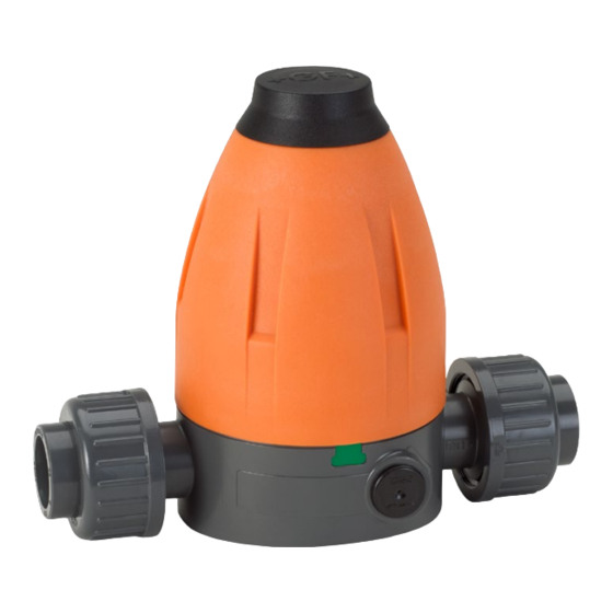
Instruction manual Design 4 Design 4.1 Pressure reducing valve * graphic identification for pressure reduction (-) pressure increase (+) Compression piece Locking nut Retaining ring Spindle/adjusting screw Diaphragm Spring retainer Piston Bonnet assembly (top part) * Body Inner spring O-rings Outer spring Inner body Diaphragm, O-rings, diaphragm washer, inner body and piston constitute the... -
Page 7: Pressure Retaining Valve
Design Instruction manual 4.2 Pressure retaining valve * graphic identification for pressure reduction (-) pressure increase (+) Pressure piece Locking nut Retaining ring Spindle/adjusting screw Diaphragm Spring retainer Piston Bonnet assembly (top part)* Body Inner spring O-rings Outer spring Inner body Diaphragm, O-rings, diaphragm washer, inner body and piston constitute the cartridge. -
Page 8: Manometer
Indication of flow direction Manometer adaptor (optional) Manometer socket Manometer If pressure reducing valve type 582/pressure retaining valve type 586 is a manometer version, then the manometer is already fitted at the factory. 5 Function 5.1 Pressure reducing valve On the side of the valve outlet, the pressure acts via the diaphragm on the adjustable spring. -
Page 9: Identification
Identification Instruction manual 6 Identification 6.1 Valve type/sealing material (O-rings) Valve type Sealing material Colour of index plate Pressure reducing valve type 582 EPDM white Pressure reducing valve type 582 green Pressure retaining valve type 586 EPDM black Pressure retaining valve type 586... -
Page 10: Required Tools
The valve bodies are suited for various connection types: Connection: radial installation and removal Connection: spigot ends Pressure reducing valves type 582/pressure retaining valves type 586 are supplied with released spring. - Page 11 Installation Instruction manual Ensure that pressure reducing valve type 582/pressure retaining valve type 586 is suited for operating conditions, see label. Check pressure reducing valve type 582/pressure retaining valve type 586 on damages before installation. Do not use any damaged or faulty product.
- Page 12 Connect the connection parts with the pipe ends. For instructions concerning the different connection types, see planning fundamentals. Put pressure reducing valve type 582/pressure retaining valve type 586 between the connection parts. Tighten the coupling nuts by hand.
-
Page 13: Operation
Operation Instruction manual 10 Operation 10.1 Pressure test Ensure that the test pressure does not exceed 1.1 times the max. set back pressure. 10.2 Setting the working pressure Remove the cap from the bonnet assembly (top part), see Fig. 2. To do so, position the screw driver in the notch of the cap. - Page 14 Ensure that the set point value is set. To do so, read the set point value at the manometer or the corresponding indicator. CAUTION Displacement of the set point value of pressure reducing valve type 582/ pressure retaining valve type 586 due to wrong locking. Fix the spindle with Allen wrench and simultaneously tighten the locking nut with a suited tool, see Fig 6 Fig.
-
Page 15: Maintenance
CAUTION Risk of injury and missing product quality through use of spare parts that have not been provided by GF Piping Systems! Only use the listed spare parts, see Chapter List of Spare Parts. Set maintenance intervals as per the conditions of use (e.g. actuating cycles, medium, ambient temperature). -
Page 16: Replacing Diaphragm And O-Ring
Instruction manual Maintenance 11.1 Replacing diaphragm and O-ring Remove the valve from the pipeline and bring it into horizontal position. 11.1.1 Disassembly Prior to dismantling: Mark the position of bonnet assembly (top part) to body on the housing. ... - Page 17 Fig. 9 Remove 2 O-rings from body, see Fig. 10 Fig. 10 In order to replace diaphragm: Replace cartridge, see Chapter “spare parts” Cartridge for pressure Cartridge for pressure reducing valve type 582 retaining valve type 586 Fig. 11...
-
Page 18: Assembly
Instruction manual Maintenance 11.1.2 Assembly Ensure that 2 O-rings sit correctly in the body. Position the cartridge in the body and push in, see Fig. 12 Replace the index plate in case of valve type or elastomer change Fig. - Page 19 Maintenance Instruction manual Put the springs on the Pressure piece, see Fig 15 Fig. 15 Put the bonnet assembly (top part) onto the body. Fix the body and tighten up to the marking/old seal sticker (see Chapter 11.1.1) +20°: DN 10/15 DN 20/25 DN 32/40/50...
-
Page 20: Cleaning The Inner Body
Dismantling, see Check and clean the area of the seat gasket, see Fig. 16 Seat gasket Example: Pressure reducing valve type 582 Fig. 16 Clean the drill holes of the inner housing, see Fig. 17 Pressure reducing valve... -
Page 21: Troubleshooting
(caution: pressure (only valid for pressure increase) reducing valve type 582) Impure function parts Clean pressure reducing valve type 582, see Chapter 11.2 Inertia too high, set point... - Page 22 (kvs value) velocities inside the valve Excessive damage of Dirty medium, corrosion Install strainer pressure reducing valve deposits or foreign type 582/pressure matter. retaining valve type 586 Manometer does not Manometer defective Replace manometer indicate anything Buffer medium escaped...
-
Page 23: Spare Parts
Read DN size at body. Read designation of spare part, see Chapter 4.1 or 4.2. Send the order with these details and the required quantity to the agency of GF Piping Systems. 14 Accessories Article number... -
Page 24: Ec Manufacturer's Declaration
Neutralize possible media residues in the product. Separate materials (plastics, metals etc.) and dispose of according to the local regulations. If you have questions regarding the disposal of your product, please contact your national GF Piping Systems representative. 16 EC Manufacturer's declaration...
Need help?
Do you have a question about the 582 and is the answer not in the manual?
Questions and answers