
Subscribe to Our Youtube Channel
Related Manuals for Stahl 9172 Series


Summary of Contents for Stahl 9172 Series
- Page 1 Betriebsanleitung Additional languages r-stahl.com Ex i Relais Modul Reihe 9172...
-
Page 2: Table Of Contents
Inhaltsverzeichnis Allgemeine Angaben ...................3 Hersteller ......................3 Zu dieser Betriebsanleitung ................3 Weitere Dokumente ....................3 Konformität zu Normen und Bestimmungen ............3 Erläuterung der Symbole ..................4 Symbole in der Betriebsanleitung ...............4 Symbole am Gerät ....................4 Sicherheit ......................5 Bestimmungsgemäße Verwendung ..............5 Qualifikation des Personals ................5 Restrisiken ......................6 Transport und Lagerung ..................8 Produktauswahl und Projektierung ..............8... -
Page 3: De De
Betriebsanleitung während der Lebensdauer des Geräts aufbewahren. Betriebsanleitung dem Bedien- und Wartungspersonal jederzeit zugänglich machen. Betriebsanleitung an jeden folgenden Besitzer oder Benutzer des Geräts weitergeben. Betriebsanleitung bei jeder von R. STAHL erhaltenen Ergänzung aktualisieren. ID-Nr.: 160372 / 9172601310 Publikationsnummer: 2021-02-25·BA00·III·de·08... -
Page 4: Erläuterung Der Symbole
Erläuterung der Symbole Erläuterung der Symbole Symbole in der Betriebsanleitung Symbol Bedeutung Hinweis zum leichteren Arbeiten GEFAHR! Gefahrensituation, die bei Nichtbeachtung der Sicherheitsmaßnahmen zum Tod oder zu schweren Verletzungen mit bleibenden Schäden führen kann. WARNUNG! Gefahrensituation, die bei Nichtbeachtung der Sicherheitsmaßnahmen zu schweren Verletzungen führen kann. -
Page 5: Sicherheit
Bereich zugelassen. Zur bestimmungsgemäßen Verwendung gehört die Beachtung dieser Betriebsanleitung, und der mitgeltenden Dokumente, z.B. des Datenblatts. Alle anderen Anwendungen sind nur nach Freigabe der Firma R. STAHL bestimmungsgemäß. Qualifikation des Personals Für die in dieser Betriebsanleitung beschriebenen Tätigkeiten ist eine entsprechend qualifizierte Fachkraft erforderlich. -
Page 6: 3.3 Restrisiken
Umgebungsbedingungen (siehe Kapitel "Technische Daten") berücksichtigen. Gerät nicht belasten. Verpackung und Gerät auf Beschädigung prüfen. Beschädigungen umgehend an R. STAHL melden. Beschädigtes Gerät nicht in Betrieb nehmen. Gerät in Originalverpackung, trocken (keine Betauung), in stabiler Lage und sicher vor Erschütterungen lagern. - Page 7 Sicherheit Unsachgemäße Montage, Installation, Inbetriebnahme, Instandhaltung oder Reinigung Grundlegende Arbeiten wie Installation, Inbetriebnahme, Instandhaltung oder Reinigung des Geräts dürfen nur nach gültigen nationalen Bestimmungen des Einsatzlandes und von qualifizierten Personen durchgeführt werden. Ansonsten kann der Explosionsschutz aufgehoben werden. Explosionen mit tödlichen oder schweren Verletzungen von Personen können die Folge sein.
-
Page 8: 4 Transport Und Lagerung
Transport und Lagerung Transport und Lagerung Gerät sorgfältig und unter Beachtung der Sicherheitshinweise (siehe Kapitel "Sicherheit") transportieren und lagern. Produktauswahl und Projektierung Schaltschrank so aufbauen und einrichten, dass alle darin installierten Geräte immer innerhalb ihres zulässigen Temperaturbereichs betrieben werden (siehe Installationsanleitung Schaltschrank). - Page 9 Montage und Installation Demontage 06881E00 Fußriegel mit dem Schraubendreher etwas herausziehen. Gerät herausschwenken. 6.1.3 Montage / Demontage auf pac-Träger Siehe Betriebsanleitung pac-Träger Typ 9195. 6.1.4 Montage / Demontage steckbare Klemmen Alle Geräte sind mit steckbaren Klemmen ausgestattet. Montage ...
-
Page 10: 6.2 Installation
Parametrierung und Inbetriebnahme Installation Bei Betrieb unter erschwerten Bedingungen wie insbesondere auf Schiffen sind zusätzliche Maßnahmen zur korrekten Installation je nach Einsatzort zu treffen. Weitere Informationen und Anweisungen hierzu erhalten Sie gerne auf Anfrage von Ihrem zuständigen Vertriebskontakt. 6.2.1 Elektrische Anschlüsse / Prinzipschaltbild Siehe Geräteaufdruck. -
Page 11: Fehlerbeseitigung
Das Gerät benötigt keine regelmäßige Wartung. Gerät gemäß den geltenden nationalen Bestimmungen und den Sicherheitshinweisen dieser Betriebsanleitung (Kapitel "Sicherheit") warten. Reparatur Reparaturen am Gerät nur durch R. STAHL durchführen lassen. 160372 / 9172601310 Ex i Relais Modul 2021-02-25·BA00·III·de·08... -
Page 12: Rücksendung
Rücksendung Rücksendung Rücksendung bzw. Verpackung der Geräte nur in Absprache mit R. STAHL durchführen! Dazu mit der zuständigen Vertretung von R. STAHL Kontakt aufnehmen. Für die Rücksendung im Reparatur- bzw. Servicefall steht der Kundenservice von R. STAHL zur Verfügung. -
Page 13: Anhang A
Anhang A Anhang A 14.1 Technische Daten Kennzeichnung Typbezeichnung 9172/ab-11-00 (a=1,2; b=0,1,2) CE-Kennzeichnung 0158 Explosionsschutz Global (IECEx) Gas und Staub IECEx BVS 09.0002X Ex ec nC [ia Ga] IIC T4 Gc [Ex ia Da] IIIC Europa (ATEX) Gas und Staub BVS 04 ATEX E 097 X E II 3 (1) G Ex ec nC [ia Ga] IIC T4 Gc E II (1) D [Ex ia Da] IIIC... - Page 14 Anhang A Technische Daten Ausführung 9172/.0-11-00 9172/.1-11-00 9172/.2-11-00 Elektrische Daten Eingang Eingangssignal Ex i Nicht-Ex i Ex i Schaltsignal 14 ... 30 V 12 ... 31,2 V 14 ... 30 V Innenwiderstand des ansteuernden Digitalausgangs beachten. Stromaufnahme < 16 mA bei 12 V <...
- Page 15 0,2 ... 1 mm – - flexibel 0,2 ... 1,5 mm – - flexibel mit Aderendhülsen 0,25 ... 1 mm 0,5 ... 1 mm Anschlussplan Siehe Geräteaufdruck Weitere technische Daten, siehe r-stahl.com. 160372 / 9172601310 Ex i Relais Modul 2021-02-25·BA00·III·de·08 Reihe 9172...
-
Page 16: Anhang B
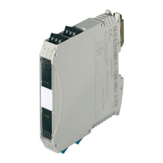
Anhang B Anhang B 15.1 Geräteaufbau Geräteelement Beschreibung Schwarze Klemmen sicherer Bereich Blaue Klemmen Ex-Bereich (Eigensicher Ex i) LED "OUT1", gelb Ausgang Kanal 1 aktiviert LED "OUT2", gelb Ausgang Kanal 2 aktiviert 9172 08584E00 15.2 Maßangaben / Befestigungsmaße Maßzeichnungen (alle Maße in mm [Zoll]) – Änderungen vorbehalten Maß... - Page 17 Operating instructions Additional languages r-stahl.com I.S. Relay Module Series 9172...
- Page 18 Contents General Information ....................3 Manufacturer .......................3 About these Operating Instructions ..............3 Further Documents .....................3 Conformity with Standards and Regulations ............3 Explanation of the Symbols ................4 Symbols in these Operating Instructions ............4 Symbols on the Device ..................4 Safety ........................5 Intended Use .......................5 Personnel Qualification ..................5 Residual Risks ....................6 Transport and Storage ..................8...
-
Page 19: En En
• FMEDA SIL Report For documents in other languages, see r-stahl.com. Conformity with Standards and Regulations • Certificates and EU Declaration of Conformity: r-stahl.com. • The device has IECEx approval. See IECEx homepage: http://iecex.iec.ch/ to view the certificate. • Further national certificates can be downloaded via the following link: https://r-stahl.com/en/global/support/downloads/. -
Page 20: Explanation Of The Symbols
Explanation of the Symbols Explanation of the Symbols Symbols in these Operating Instructions Symbol Meaning Tip for making work easier DANGER! Dangerous situation which can result in fatal or severe injuries causing permanent damage if the safety measures are not complied with. -
Page 21: Safety
"Intended use" includes complying with these operating instructions and the other applicable documents, e.g. the data sheet. All other uses are only intended after being approved by R. STAHL. Personnel Qualification Qualified specialist personnel are required to perform the activities described in these operating instructions. -
Page 22: 3.3 Residual Risks
(see the "Technical data" chapter). Do not place any loads on the device. Check the packaging and the device for damage. Report any damage to R. STAHL immediately. Do not commission a damaged device. Store the device in its original packaging in a dry place (with no condensation), and make sure that it is stable and protected against the effects of vibrations and knocks. - Page 23 Safety Improper mounting, installation, commissioning, maintenance or cleaning Basic work such as installation, commissioning, maintenance or cleaning of the device must always be performed in accordance with the applicable national regulations of the country of use and only by qualified persons. Otherwise, the explosion protection may be rendered ineffective.
-
Page 24: 4 Transport And Storage
Transport and Storage Transport and Storage Transport and store the device carefully and in accordance with the safety notes (see Chapter "Safety"). Product Selection and Project Engineering Install and set up the cabinet in such a way that all devices installed within it are always operated within their permissible temperature range (see cabinet installation guide). - Page 25 Mounting and Installation Dismounting 06881E00 Pull out the base bolt slightly using a screwdriver. Swivel out the device. 6.1.3 Mounting / Dismounting on pac-Carrier See operating instructions for pac-Carrier Type 9195. 6.1.4 Mounting / Dismounting pluggable Terminals All devices are equipped with pluggable terminals. Mounting ...
-
Page 26: 6.2 Installation
Parameterization and Commissioning Installation Operation under difficult conditions, in particular on ships, requires additional measures to be taken for correct installation, depending on the operating location. Further information and instructions on this can be obtained from your regional sales contact upon request. 6.2.1 Electrical Connections / Schematic Diagram See device labelling. -
Page 27: Troubleshooting
Perform maintenance on the device according to the applicable national regulations and the safety notes in these operating instructions ("Safety" chapter). Repair Repair work on the device must be performed only by R. STAHL. 160372 / 9172601310 I.S. Relay Module 2021-02-25·BA00·III·en·08... -
Page 28: Returning The Device
Only return or package the devices after consulting R. STAHL! Contact the responsible representative from R. STAHL. R. STAHL's customer service is available to handle returns if repair or service is required. Contact customer service personally. Go to the r-stahl.com website. -
Page 29: Annex A
Annex A Annex A 14.1 Technical Data Marking Type designation 9172/ab-11-00 (a=1,2; b=0,1,2) CE marking 0158 Explosion Protection Global (IECEx) Gas and dust IECEx BVS 09.0002X Ex ec nC [ia Ga] IIC T4 Gc [Ex ia Da] IIIC Europe (ATEX) Gas and dust BVS 04 ATEX E 097 X E II 3 (1) G Ex ec nC [ia Ga] IIC T4 Gc... - Page 30 Annex A Technical Data Version 9172/.0-11-00 9172/.1-11-00 9172/.2-11-00 Electrical data Input Input signal Ex i non-Ex i Ex i Switching signal 14 to 30 V 12 to 31.2 V 14 to 30 V Note the internal resistance of the triggering digital output. Current <...
- Page 31 - flexible 0.2 to 1.5 mm – - flexible with core end sleeve 0.25 to 1 mm 0.5 to 1 mm Connection diagram See device labelling For further technical data, see r-stahl.com. 160372 / 9172601310 I.S. Relay Module 2021-02-25·BA00·III·en·08 Series 9172...
-
Page 32: Annex B
Annex B Annex B 15.1 Device Design Device component Description Black terminals Safe area Blue terminals Hazardous area (intrinsically safe Ex i) LED "OUT1", yellow Output channel 1 activated LED "OUT2", yellow Output channel 2 activated 9172 08584E00 15.2 Dimensions / Fastening Dimensions Dimensional drawings (all dimensions in mm [inches]) –... - Page 34 Type 9172/*0-11-00 Type 9172/*1-11-00 Type 9172/*2-11-00 (only at (only at (only at 9172/20) 9172/21) 9172/22) Hazardous area: Class I, II, III; DIV 1; Group A-G or Class I; Zone 0; Group IIC/IIB Hazardous Locations Safe area: Non-hazardous; Division 2 or Zone 2 Hazardous (Classified) Locations The Relay Module Type 9172 is an associated apparatus as well as a nonincendive apparatus for installation in non-hazardous or Class I, Division 2 or Zone 2 Hazardous (Classified) Locations and provides intrinsically safe connections for one (or two) field devices located in Class I, II, III, Division 1, Group A-G or Class I, Zone 0 [AEx ia] Group IIC, hazardous locations according to NEC Article 504/505 as listed...
Need help?
Do you have a question about the 9172 Series and is the answer not in the manual?
Questions and answers