Chapters
Table of Contents

Related Manuals for Stahl 9491 Series


Summary of Contents for Stahl 9491 Series
- Page 1 Betriebsanleitung Additional languages r-stahl.com Anschlussboard und Verbindungskabel für Zone 2 Reihe 9491...
-
Page 2: Table Of Contents
Inhaltsverzeichnis Allgemeine Angaben ...................3 Hersteller ......................3 Zu dieser Betriebsanleitung ................3 Weitere Dokumente ....................3 Konformität zu Normen und Bestimmungen ............3 Erläuterung der Symbole ..................4 Symbole in der Betriebsanleitung ...............4 Symbole am Gerät ....................4 Sicherheit ......................5 Bestimmungsgemäße Verwendung ..............5 Qualifikation des Personals ................5 Restrisiken ......................6 Transport und Lagerung ..................8 Produktauswahl und Projektierung ..............8... -
Page 3: De De
Betriebsanleitung während der Lebensdauer des Geräts aufbewahren. Betriebsanleitung dem Bedien- und Wartungspersonal jederzeit zugänglich machen. Betriebsanleitung an jeden folgenden Besitzer oder Benutzer des Geräts weitergeben. Betriebsanleitung bei jeder von R. STAHL erhaltenen Ergänzung aktualisieren. ID-Nr.: 276285 / 949160310010 Publikationsnummer: 2021-05-06·BA00·III·de·00... -
Page 4: Erläuterung Der Symbole
Erläuterung der Symbole Erläuterung der Symbole Symbole in der Betriebsanleitung Symbol Bedeutung Hinweis zum leichteren Arbeiten GEFAHR! Gefahrensituation, die bei Nichtbeachtung der Sicherheitsmaßnahmen zum Tod oder zu schweren Verletzungen mit bleibenden Schäden führen kann. WARNUNG! Gefahrensituation, die bei Nichtbeachtung der Sicherheitsmaßnahmen zu schweren Verletzungen führen kann. -
Page 5: Sicherheit
Normen und Bestimmungen umfasst. Für Tätigkeiten in explosionsgefährdeten Bereichen sind weitere Kenntnisse erforderlich! R. STAHL empfiehlt einen Kenntnisstand, der in folgenden Normen beschrieben wird: • IEC/EN 60079-14 (Projektierung, Auswahl und Errichtung elektrischer Anlagen) • IEC/EN 60079-17 (Prüfung und Instandhaltung elektrischer Anlagen) •... -
Page 6: 3.3 Restrisiken
Umgebungsbedingungen (siehe Kapitel "Technische Daten") berücksichtigen. Verpackung und Gerät auf Beschädigung prüfen. Beschädigungen umgehend an R. STAHL melden. Beschädigtes Gerät nicht in Betrieb nehmen. Gerät in Originalverpackung, trocken (keine Betauung), in stabiler Lage und sicher vor Erschütterungen lagern. - Page 7 Nur kompatible Komponenten anschließen (Remote I/O-System IS1+/IS1). Im Zweifelsfall Rücksprache mit R. STAHL halten. Reparaturen am Gerät nur durch R. STAHL durchführen lassen. Gerät nur mit feuchtem Tuch und ohne kratzende, scheuernde oder aggressive Reinigungsmittel oder Lösungen schonend reinigen.
-
Page 8: Produktauswahl Und Projektierung
Transport und Lagerung Transport und Lagerung Gerät sorgfältig und unter Beachtung der Sicherheitshinweise (siehe Kapitel "Sicherheit") transportieren und lagern. Produktauswahl und Projektierung Bei der Projektierung Folgendes beachten: • Die Installation des Geräts ist nur zulässig, wenn es gemäß seiner bestimmungsgemäßen Verwendung eingesetzt wird, siehe Kapitel 3.1. -
Page 9: Montage Und Installation
Montage und Installation Montage und Installation Montage / Demontage Gerät sorgfältig und nur unter Beachtung der Sicherheitshinweise (siehe Kapitel "Sicherheit") montieren. Folgende Einbaubedingungen und Montageanweisungen genau durchlesen und exakt befolgen. 6.1.1 Gebrauchslage • Das Anschlussboard Typ 9491/T1-..-0. kann in beliebiger Gebrauchslage auf einer Hutschiene montiert werden. -
Page 10: Montage / Demontage
Montage und Installation Demontage 22372E00 Beide Schnappriegel mit einem Schraubendreher nacheinander aufhebeln. Unterkante des Gerätes nach vorne schwenken und das Gerät nach oben entnehmen. Installation Bei Betrieb unter erschwerten Bedingungen wie insbesondere auf Schiffen sind zusätzliche Maßnahmen zur korrekten Installation je nach Einsatzort zu treffen. Weitere Informationen und Anweisungen hierzu erhalten Sie gerne auf Anfrage von Ihrem zuständigen Vertriebskontakt. - Page 11 Montage und Installation Anschluss zwischen I/O-Modulen und Anschlussboard Das Anschlussboard 9491/T1-08-0. in Kombination mit zwei Verbindungskabel 9491/Z1-VB-.. ermöglicht die redundante Zusammenschaltung zweier I/O-Module Typ 9469/35. primäres redundantes I/O Modul I/O Modul 1 2 3 4 5 6 7 8 9 10 11 12 1 2 3 4 5 6 7 8 9 10 11 12 22373E00 ...
- Page 12 Montage und Installation Anschluss der Feldgeräte am Anschlussboard Die Ein- und Ausgangssignale an Klemmen X1 der I/O-Module werden an den Klemmen X1A und X1B des Anschlussboards weitergegeben. 9469/35-08-11 9491/T1-08-0. Kanal Klemme Klem- Funktion Klemme Klem- men-Nr. men-Nr. 2-Leiter MU 3- / 4-Leiter MU AI / AO AI (ext.
- Page 13 Montage und Installation 6.2.2 Anschlussboard Typ 9491/T1-16-0. GEFAHR! Explosionsgefahr durch Zündfunken bei Arbeiten an einem nicht sicher befestigten Gerät! Nichtbeachten führt zu tödlichen oder schweren Verletzungen. Schrauben mit angegebenen Anzugsdrehmomenten anziehen. GEFAHR! Explosionsgefahr durch Zündfunken aufgrund fehlender Isolierung! Nichtbeachten führt zu tödlichen oder schweren Verletzungen. ...
- Page 14 Montage und Installation Anschluss der Feldgeräte am Anschlussboard Die Ausgangssignale an Klemmen X1 und X2 der I/O-Module werden an den Klemmen X1A, X1B, X2A und X2B des Anschlussboards weitergegeben. 9471/35 und 9472/35 9491/T1-16-0. Kanal Klemme Klem- Funktion (DO) Klemme Klem- men-Nr.
- Page 15 Montage und Installation 9471/35 und 9472/35 9491/T1-16-0. Kanal Klemme Klem- Funktion (DO) Klemme Klem- men-Nr. men-Nr. 9472/35-16-11 9471/35-16-11 Ausgang (+24 V) Signal Signal Masse (GND) Masse (GND) Ausgang (+24 V) Signal Signal Masse (GND) Masse (GND) Ausgang (+24 V) Signal Signal Masse (GND) Masse (GND)
-
Page 16: Parametrierung Und Inbetriebnahme
Das Gerät benötigt keine regelmäßige Wartung. Gerät gemäß den geltenden nationalen Bestimmungen und den Sicherheitshinweisen dieser Betriebsanleitung (Kapitel "Sicherheit") warten. Reparatur Reparaturen am Gerät nur durch R. STAHL durchführen lassen. Anschlussboard und Verbindungskabel 276285 / 949160310010 für Zone 2 2021-05-06·BA00·III·de·00... -
Page 17: Rücksendung
Rücksendung Rücksendung Rücksendung bzw. Verpackung der Geräte nur in Absprache mit R. STAHL durchführen! Dazu mit der zuständigen Vertretung von R. STAHL Kontakt aufnehmen. Für die Rücksendung im Reparatur- bzw. Servicefall steht der Kundenservice von R. STAHL zur Verfügung. -
Page 18: Anhang A
Anhang A Anhang A 14.1 Technische Daten Explosionsschutz Global (IECEx) IECEx TUR 19.0072X Ex ec IIC T4 Gc Europa (ATEX) TÜV 19 ATEX 8462 X E II 3 G Ex ec IIC T4 Gc Bescheinigungen und Zulassungen Bescheinigungen IECEx, ATEX Weitere Parameter Installation in Zone 2, Zone 22 und im sicheren Bereich... - Page 19 Leiterquerschnitt - starr 0,2 ... 4 mm (AWG 24 ... AWG 14) - flexibel 0,2 ... 1,5 mm (AWG 24 ... AWG 16) Weitere technische Daten, siehe r-stahl.com. 276285 / 949160310010 Anschlussboard und Verbindungskabel 2021-05-06·BA00·III·de·00 für Zone 2 Reihe 9491...
-
Page 20: Anhang B
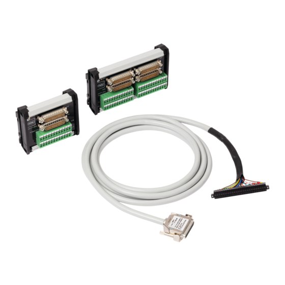
Anhang B Anhang B 15.1 Geräteaufbau 22375E00 Typ 9491/T1-08-0. 22376E00 Typ 9491/T1-16-0. Gerätelement Beschreibung Erdungskontakt Elektrische Verbindung Kabelschirm mit Hutschiene Schnappriegel Zur Befestigung des Geräts auf die Hutschiene Sub-D-Buchse (X1P) Zum Anschluss an I/O-Modul Sub-D-Buchse (X1R) Zum Anschluss an I/O-Modul Klemme (X1B) Zur feldseitigen Verdrahtung Klemme (X1A) -
Page 21: 15.2 Maßangaben / Befestigungsmaße
Anhang B 15.2 Maßangaben / Befestigungsmaße Maßzeichnungen (alle Maße in mm [Zoll]) – Änderungen vorbehalten 22231E00 22230E00 Typ 9491/T1-08-0. Typ 9491/T1-16-0. 276285 / 949160310010 Anschlussboard und Verbindungskabel 2021-05-06·BA00·III·de·00 für Zone 2 Reihe 9491... - Page 23 Operating instructions Additional languages r-stahl.com Termination board and connecting cable for Zone 2 Series 9491...
- Page 24 Contents General Information ....................3 Manufacturer .......................3 About these Operating Instructions ..............3 Further Documents .....................3 Conformity with Standards and Regulations ............3 Explanation of the Symbols ................4 Symbols in these Operating Instructions ............4 Symbols on the Device ..................4 Safety ........................5 Intended Use .......................5 Personnel Qualification ..................5 Residual Risks ....................6 Transport and Storage ..................8...
-
Page 25: En En
• IS1+ coupling description (download from r-stahl.com) For documents in other languages, see r-stahl.com. Conformity with Standards and Regulations • Certificates and EU Declaration of Conformity: r-stahl.com. • The device has IECEx approval. See IECEx homepage: http://iecex.iec.ch/ to view the certificate. -
Page 26: Explanation Of The Symbols
Explanation of the Symbols Explanation of the Symbols Symbols in these Operating Instructions Symbol Meaning Tip for making work easier DANGER! Dangerous situation which can result in fatal or severe injuries causing permanent damage if the safety measures are not complied with. -
Page 27: Safety
Specialists who perform these tasks must have a level of knowledge that meets applicable national standards and regulations. Additional knowledge is required for tasks in hazardous areas! R. STAHL recommends having a level of knowledge equal to that described in the following standards: •... -
Page 28: 3.3 Residual Risks
Observe the ambient conditions when selecting the transport packaging (see the "Technical data" chapter). Check the packaging and the device for damage. Report any damage to R. STAHL immediately. Do not commission a damaged device. Store the device in its original packaging in a dry place (with no condensation), and make sure that it is stable and protected against the effects of vibrations and knocks. - Page 29 Only connect compatible components (IS1+/IS1 Remote I/O system). When in doubt, consult R. STAHL. Repair work on the device must be performed only by R. STAHL. Gently clean the device with a damp cloth only – do not use scratching, abrasive or aggressive cleaning agents or solutions.
-
Page 30: 4 Transport And Storage
Transport and Storage Transport and Storage Transport and store the device carefully and in accordance with the safety notes (see Chapter "Safety"). Product Selection and Project Engineering The following conditions must be observed during project engineering: • Installation of the device is permissible only if it is used in accordance with its intended use; see chapter 3.1. -
Page 31: Mounting And Installation
Mounting and Installation Mounting and Installation Mounting / Dismounting Mount the device carefully and only in accordance with the safety notes (see Chapter "Safety"). Read through the following installation conditions and assembly instructions carefully and follow them precisely. 6.1.1 Operating Position •... -
Page 32: Installation
Mounting and Installation Dismounting 22372E00 Pry open both snap catches one after the other with a screwdriver. Swing the bottom edge of the device forwards and move the device upwards to remove it. Installation Operation under difficult conditions, in particular on ships, requires additional measures to be taken for correct installation, depending on the operating location. - Page 33 Mounting and Installation Connection between I/O modules and termination board The termination board 9491/T1-08-0. in combination with two connecting cables 9491/Z1-VB-.. enables the redundant interconnection of two type 9469/35 I/O modules. primary redundant I/O module I/O module 1 2 3 4 5 6 7 8 9 10 11 12 1 2 3 4 5 6 7 8 9 10 11 12 22373E00 ...
- Page 34 Mounting and Installation Connecting the field devices to the termination board The input and output signals on the X1 terminals of the I/O modules are passed on to the X1A and X1B terminals of the termination board. 9469/35-08-11 9491/T1-08-0. Channel Terminal Terminal Function Terminal Terminal 2-wire...
- Page 35 Mounting and Installation 6.2.2 Termination Board Type 9491/T1-16-0. DANGER! Explosion hazard due to ignition sparks during work on a device that has not been fitted securely! Non-compliance may result in fatal or serious injuries. Tighten the screws to the specified tightening torques. DANGER! Explosion hazard due to ignition sparks caused by insufficient insulation! Non-compliance may result in fatal or serious injuries.
- Page 36 Mounting and Installation Connecting the field devices to the termination board The output signals on the X1 and X2 terminals of the I/O modules are passed on to the X1A, X1B, X2A and X2B terminals of the termination board. 9471/35 and 9472/35 9491/T1-16-0.
- Page 37 Mounting and Installation 9471/35 and 9472/35 9491/T1-16-0. Channel Terminal Terminal Function (DO) Terminal Terminal 9472/35-16-11 9471/35-16-11 Output (+24 V) Signal Signal Earth Earth Output (+24 V) Signal Signal Earth Earth Output (+24 V) Signal Signal Earth Earth Output (+24 V) Signal Signal Earth...
-
Page 38: Parameterization And Commissioning
Perform maintenance on the device according to the applicable national regulations and the safety notes in these operating instructions ("Safety" chapter). Repair Repair work on the device must be performed only by R. STAHL. Termination board and 276285 / 949160310010 connecting cable for Zone 2 2021-05-06·BA00·III·en·00... -
Page 39: Returning The Device
Only return or package the devices after consulting R. STAHL! Contact the responsible representative from R. STAHL. R. STAHL's customer service is available to handle returns if repair or service is required. Contact customer service personally. Go to the r-stahl.com website. -
Page 40: Annex A
Annex A Annex A 14.1 Technical Data Explosion Protection Global (IECEx) IECEx TUR 19.0072X Ex ec IIC T4 Gc Europe (ATEX) TÜV 19 ATEX 8462 X E II 3 G Ex ec IIC T4 Gc Certifications and certificates Certificates IECEx, ATEX Further parameters Installation In Zone 2, Zone 22 and in the safe area... - Page 41 0.2 to 4 mm (AWG 24 to AWG 14) - flexible 0.2 to 1.5 mm (AWG 24 to AWG 16) For further technical data, see r-stahl.com. 276285 / 949160310010 Termination board and 2021-05-06·BA00·III·en·00 connecting cable for Zone 2 Series 9491...
-
Page 42: Annex B
Annex B Annex B 15.1 Device Design 22375E00 Type 9491/T1-08-0. 22376E00 Type 9491/T1-16-0. Device component Description Earthing contact Electrical connection between cable shield and DIN rail Snap catch For mounting the device on the DIN rail Sub-D socket (X1P) For connection to the I/O module Sub-D socket (X1R) For connection to the I/O module Terminal (X1B) -
Page 43: 15.2 Dimensions / Fastening Dimensions
Annex B 15.2 Dimensions / Fastening Dimensions Dimensional drawings (all dimensions in mm [inches]) – Subject to alteration 22231E00 22230E00 Type 9491/T1-08-0. Type 9491/T1-16-0. 276285 / 949160310010 Termination board and 2021-05-06·BA00·III·en·00 connecting cable for Zone 2 Series 9491...
Need help?
Do you have a question about the 9491 Series and is the answer not in the manual?
Questions and answers