Chapters
Table of Contents

Related Manuals for Stahl 9442/35 Series


Summary of Contents for Stahl 9442/35 Series
- Page 1 Betriebsanleitung Additional languages www.r-stahl.com CPU Modul für Zone 2 / Division 2 Reihe 9442/35...
-
Page 2: Table Of Contents
Inhaltsverzeichnis Allgemeine Angaben ...................3 Hersteller ......................3 Zu dieser Betriebsanleitung ................3 Weitere Dokumente ....................3 Konformität zu Normen und Bestimmungen ............3 Erläuterung der Symbole ..................4 Symbole in der Betriebsanleitung ...............4 Symbole am Gerät ....................4 Sicherheit ......................5 Bestimmungsgemäße Verwendung ..............5 Qualifikation des Personals ................5 Restrisiken ......................6 Transport und Lagerung ..................8 Produktauswahl und Projektierung ..............8... -
Page 3: De De
Betriebsanleitung während der Lebensdauer des Geräts aufbewahren. Betriebsanleitung dem Bedien- und Wartungspersonal jederzeit zugänglich machen. Betriebsanleitung an jeden folgenden Besitzer oder Benutzer des Geräts weitergeben. Betriebsanleitung bei jeder von R. STAHL erhaltenen Ergänzung aktualisieren. ID-Nr.: 264707 / 944260310010 Publikationsnummer: 2018-10-09·BA00·III·de·01... -
Page 4: Erläuterung Der Symbole
Erläuterung der Symbole Erläuterung der Symbole Symbole in der Betriebsanleitung Symbol Bedeutung Hinweis zum leichteren Arbeiten GEFAHR! Gefahrensituation, die bei Nichtbeachtung der Sicherheitsmaßnahmen zum Tod oder zu schweren Verletzungen mit bleibenden Schäden führen kann. WARNUNG! Gefahrensituation, die bei Nichtbeachtung der Sicherheitsmaßnahmen zu schweren Verletzungen führen kann. -
Page 5: Sicherheit
Normen und Bestimmungen umfasst. Für Tätigkeiten in explosionsgefährdeten Bereichen sind weitere Kenntnisse erforderlich! R. STAHL empfiehlt einen Kenntnisstand, der in folgenden Normen beschrieben wird: • IEC/EN 60079-14 (Projektierung, Auswahl und Errichtung elektrischer Anlagen) • IEC/EN 60079-17 (Prüfung und Instandhaltung elektrischer Anlagen) •... -
Page 6: 3.3 Restrisiken
Umgebungsbedingungen (siehe Kapitel "Technische Daten") berücksichtigen. Gerät nicht belasten. Verpackung und Gerät auf Beschädigung prüfen. Beschädigungen umgehend an R. STAHL melden. Beschädigtes Gerät nicht in Betrieb nehmen. Gerät in Originalverpackung, trocken (keine Betauung), in stabiler Lage und sicher vor Erschütterungen lagern. - Page 7 Nur kompatible Komponenten anschließen (Remote I/O System IS1+/IS1). Im Zweifelsfall Rücksprache mit R. STAHL halten. Reparaturen am Gerät nur durch R. STAHL durchführen lassen. Gerät nur mit feuchtem Tuch und ohne kratzende, scheuernde oder aggressive Reinigungsmittel oder Lösungen schonend reinigen.
-
Page 8: 4 Transport Und Lagerung
Transport und Lagerung 3.3.2 Beschädigung elektrischer Komponenten Empfindliche elektronische Bauteile können durch elektrostatische Entladung (ESD) beschädigt werden. Vor dem Kontakt mit dem Gerät an einem geerdeten metallischen Körper entladen. Direkte Berührung von Steckverbindern oder Kontakten der Modulsteckplätze vermeiden. ... -
Page 9: Anschlussbelegung Sub-D-Buchse X1
Produktauswahl und Projektierung Projektierungsvorgaben in Abhängigkeit der Umgebungstemperatur Befestigung je nach maximaler Umgebungstemperatur ausrichten, siehe Kapitel "Technische Daten". Update/Austausch von Modulen • Kapitel "Austausch und Upgrade des Moduls" beachten. Anschlussbelegung Sub-D-Buchse X1 Für den Anschluss des PROFIBUS DP: Pin-Nr. Funktion Beschreibung RxD/TxD (+) Daten B (+) -
Page 10: Redundanz
Montage und Installation Redundanz Das IS1+ Remote I/O-System kann je nach Kommunikationsprotokoll auch redundant ausgeführt werden. Dabei wird zwischen CPU-, Power- und System-/Vollredundanz unterschieden. Auswahl des geeigneten Sockels 9496/35 und die maximale Bestückung der CPU Module 9442/35 und Power Module 9445/35 beachten! Folgende Tabelle zeigt die benötigten Komponenten für die jeweiligen Redundanzkonzepte: Sockel 9496/35 CPU Modul 9442/35... - Page 11 Montage und Installation 6.1.1 Gebrauchslage Sockel ausschließlich wie folgt montieren: • Montagelage horizontal mit Leserichtung von links, oder • Montagelage vertikal mit Leserichtung von unten oder von oben. • Der Einsatz einer Montageplatte wird empfohlen. 19629E00 6.1.2 Montage auf Sockel 9496/35 GEFAHR! Explosionsgefahr durch unzureichende Befestigung! Nichtbeachten führt zu tödlichen oder schweren Verletzungen.
-
Page 12: 6.2 Austausch Und Upgrade Des Moduls
Montage und Installation Austausch und Upgrade des Moduls 6.2.1 Austausch des CPU Moduls 9442/35 Stromversorgung des IS1+ Remote I/O-System abschalten. Anschlussleitungen für Kommunikation trennen. Sicherungsschraube (1) mit einem Schraubendreher (Torx T20) lösen, Modul nach vorne ausschwenken (2) und vom Sockel entnehmen (3). 19648E00 ... -
Page 13: Installation
Montage und Installation Installation Bei Betrieb unter erschwerten Bedingungen wie insbesondere auf Schiffen sind zusätzliche Maßnahmen zur korrekten Installation je nach Einsatzort zu treffen. Weitere Informationen und Anweisungen hierzu erhalten Sie gerne auf Anfrage von Ihrem zuständigen Vertriebskontakt. Mitgelieferte IP30 Abdeckungen müssen bei nicht genutzten Ports/Schnittstellen (RJ45/USB) aufgesteckt werden. -
Page 14: Parametrierung Und Inbetriebnahme
Parametrierung und Inbetriebnahme 6.3.2 Ethernet anschließen 19636E00 Primäre Ethernet-Leitung mit Rasthaken am Standard RJ45 Steckverbinder an die RJ45 Buchse X2P1 anschließen, bis dieser hörbar einrastet. Sekundäre Ethernet-Leitung mit Rasthaken am Standard RJ45 Steckverbinder an die RJ45 Buchse X2P2 anschließen, bis dieser hörbar einrastet. ... -
Page 15: Betrieb
Betrieb Betrieb Betrieb Zum Betrieb des Geräts die Informationen im Kapitel "Bestimmungsgemäße Verwendung" und "Parametrierung und Inbetriebnahme" beachten. Anzeigen Entsprechende LEDs am Gerät zeigen den Betriebszustand des Geräts an (siehe auch Kapitel "Bestimmungsgemäße Verwendung" und "Geräteaufbau"). Farbe Bedeutung grün Betriebsanzeige Anzeige Modulfehler blau... - Page 16 Betrieb Fehler Status Fehlerursache Fehlerbehebung LED "M/S" blau Wartungsbedarf Wartungsbedarf Modultausch empfohlen leuchtet des Moduls aufgrund der Betriebs- bedingungen LED "M/S" blau Außerhalb Übertemperatur/ Die Temperatur um die blinkt und Spezifikation Untertemperatur CPU ist zu hoch oder LED "PWR" grün zu niedrig.
- Page 17 • Gegebenenfalls unbenutzt bleibt Ethernet-Leitung tauschen Wenn sich der Fehler mit den genannten Vorgehensweisen nicht beheben lässt: An R. STAHL Schaltgeräte GmbH wenden. Zur schnellen Bearbeitung folgende Angaben bereithalten: • Typ und Seriennummer des Geräts • DCS/SPS • Protokoll •...
-
Page 18: Instandhaltung, Wartung, Reparatur
Reparaturen am Gerät nur durch R. STAHL durchführen lassen. Rücksendung Rücksendung bzw. Verpackung der Geräte nur in Absprache mit R. STAHL durchführen! Dazu mit der zuständigen Vertretung von R. STAHL Kontakt aufnehmen. Für die Rücksendung im Reparatur- bzw. Servicefall steht der Kundenservice von R. STAHL zur Verfügung. -
Page 19: Reinigung
Zubehör und Ersatzteile HINWEIS! Fehlfunktion oder Geräteschaden durch den Einsatz nicht originaler Bauteile. Nichtbeachten kann zu Sachschäden führen. Nur Original-Zubehör und Original-Ersatzteile der R. STAHL Schaltgeräte GmbH (siehe Datenblatt) verwenden. 264707 / 944260310010 CPU Modul für Zone 2 / Division 2 2018-10-09·BA00·III·de·01... -
Page 20: Anhang A
Anhang A Anhang A 14.1 Technische Daten Explosionsschutz Global (IECEx) IECEx PTB 17.0031X Ex ec ia [ia Ga] IIC T4 Gc Europa (ATEX) PTB 17 ATEX 2019 X E II 3 (1) G Ex ec ia [ia Ga] IIC T4 Gc Bescheinigungen und Zulassungen Bescheinigungen IECEx, ATEX, cFMus (Kanada, USA), EAC (Eurasische Wirtschaftsunion),... - Page 21 Anhang A Technische Daten Schnittstelle Ethernet Anschluss 2 x RJ45 Stecker, 100BASE-TX, Unmanaged Switch Funktion Protokolle Modbus TCP (PROFINET, EtherNet/IP in Vorbereitung) (vom Anwender über Drehschalter am Sockel 9496/35 wählbar) IP-Adress- manuell oder DHCP Zuweisung (vom Anwender über via Webserver oder einstellung IS1+ Detect Software wählbar.
- Page 22 Hersteller, Typ, HW-Revision, SW-Revision, Seriennummer Anschließbare • IS Wizard (über USB Service Bus) Softwarepakete • R. STAHL Geräte DTM mit fdt-Frames (z.B. fdtContainer von M+M; Pactware) • AMS von Emerson Process Management • PDM von Siemens • PRM und Fieldmate von Yokogawa •...
- Page 23 CPU Modul mit Sockel: L = 167 mm, B = 96 mm, H = 152 mm Montage / Installation Einbaubedingungen Montageart auf Sockel 9496/35 Einbaulage horizontal oder vertikal Weitere technische Daten, siehe www.r-stahl.com. 264707 / 944260310010 CPU Modul für Zone 2 / Division 2 2018-10-09·BA00·III·de·01 Reihe 9442/35...
-
Page 24: Anhang B
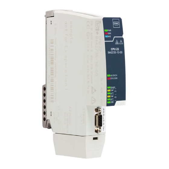
Anhang B Anhang B 15.1 Geräteaufbau Gerätelement Beschreibung Sicherungs- Torx T20 zum schraube Befestigen am Sockel LEDs Status- bzw. Fehleranzeige der LEDs Status- bzw. Fehleranzeige der Kommunikation zum Automatisierungs- system LEDs Statusanzeige der Schnittstellen 19622E00 RS485 Buchse Sub-D Buchse X1 Prozessbus Schutzkappe Schutz und... -
Page 25: 15.2 Maßangaben / Befestigungsmaße
Anhang B 15.2 Maßangaben / Befestigungsmaße Maßzeichnungen (alle Maße in mm [Zoll]) – Änderungen vorbehalten 183 [7,20] 158 [6,22] 19668E00 CPU Modul 9442/35 185 [7,28] 167 [6,57] 19670E00 CPU Modul 9442/35 mit Sockel 9496/35 264707 / 944260310010 CPU Modul für Zone 2 / Division 2 2018-10-09·BA00·III·de·01 Reihe 9442/35... -
Page 26: Anhang C
Für weitere Informationen zu Garantieansprüchen an die Autoren der mit den IS1+ 9442 CPUs ausgelieferten Open Source Software verweisen wir auf die GPL und die LGPL. Wir schließen jede Haftung für Schäden aus, die durch von anderen als R. STAHL durchgeführte Änderungen an Teilen der Software oder ihrer Konfiguration entstanden sind. - Page 27 Operating instructions Additional languages www.r-stahl.com CPU module for Zone 2 / Division 2 Series 9442/35...
- Page 28 Contents General Information ....................3 Manufacturer .......................3 About these Operating Instructions ..............3 Further Documents .....................3 Conformity with Standards and Regulations ............3 Explanation of the Symbols ................4 Symbols in these Operating Instructions ............4 Symbols on the Device ..................4 Safety ........................5 Intended Use .......................5 Personnel Qualification ..................5 Residual Risks ....................6 Transport and Storage ..................8...
-
Page 29: En En
2018-10-09·BA00·III·en·01 The original instructions are the German edition. They are legally binding in all legal affairs. Further Documents • IS1 coupling descriptions + (download from www.r-stahl.com) • 9442/35 data sheet • 9445/35 data sheet • 9496/35 data sheet • Installation of RS485 •... -
Page 30: Explanation Of The Symbols
Explanation of the Symbols Explanation of the Symbols Symbols in these Operating Instructions Symbol Meaning Tip for making work easier DANGER! Dangerous situation which can result in fatal or severe injuries causing permanent damage if the safety measures are not complied with. -
Page 31: Safety
Specialists who perform these tasks must have a level of knowledge that meets applicable national standards and regulations. Additional knowledge is required for tasks in hazardous areas! R. STAHL recommends having a level of knowledge equal to that described in the following standards: •... -
Page 32: 3.3 Residual Risks
(see the "Technical data" chapter). Do not place any load on the device. Check the packaging and the device for damage. Report any damage to R. STAHL immediately. Do not commission a damaged device. Store the device in its original packaging in a dry place (with no condensation), and make sure that it is stable and protected against the effects of vibrations and knocks. - Page 33 Only connect compatible components (IS1+/IS1 Remote I/O system). When in doubt, consult with R. STAHL. Repair work on the device must be performed only by R. STAHL. Gently clean the device only with a damp cloth and without scratching, abrasive or aggressive cleaning agents or solutions.
-
Page 34: 4 Transport And Storage
Transport and Storage 3.3.2 Damage to electrical Components Sensitive electronic components can be damaged by electrostatic discharge (ESD). Before making contact with the device, discharge the charge to an earthed metal body. Avoid direct contact with connectors or the contacts on the module slots. ... -
Page 35: Terminal Assignment For Sub-D Slot X1
Product Selection and Project Engineering Project engineering specifications depending on the ambient temperature Adjust mounting processes based on the maximum ambient temperature, see the "Technical Data" chapter. Update/replacement of modules • Observe the "Replacing and upgrading the module" chapter. Terminal Assignment for Sub-D Slot X1 For connecting the PROFIBUS DP: Pin No. -
Page 36: Redundancy
Mounting and Installation Redundancy The IS1+ Remote I/O system can also be implemented redundantly based on the communication protocol. Here, a distinction is made between CPU redundancy, power redundancy and system redundancy/full redundancy. Comply with the specifications for selecting the suitable 9496/35 base and maximum equipping of the 9442/35 CPU modules and 9445/35 power modules! The following table shows the components required for the respective redundancy concepts: 9496/35 base... - Page 37 Mounting and Installation 6.1.1 Operating Position Mount the base exclusively as follows: • Horizontal mounting position with a reading direction from left • Vertical mounting position with an upward or downward reading direction. • Use of a mounting plate is recommended. 19629E00 6.1.2 Mounting on the 9496/35 Base DANGER! Explosion hazard due to insecure mounting!
-
Page 38: 6.2 Replacing And Upgrading The Module
Mounting and Installation Replacing and Upgrading the Module 6.2.1 Replacing the 9442/35 CPU Module Switch off the power supply to the IS1+ Remote I/O system. Disconnect the connection lines for communication. Use a screwdriver (Torx T20) to unscrew the safety screw (1), swivel the module forward and out (2) and disconnect it from the base (3). -
Page 39: Installation
Mounting and Installation Installation Operation under difficult conditions, in particular on ships, requires additional measures to be taken for correct installation, depending on the operating location. Further information and instructions on this can be obtained from your regional sales contact upon request. IP30 coverings included in the delivery must be used for non-used ports/interfaces (RJ45/USB). -
Page 40: Parameterization And Commissioning
Parameterization and Commissioning 6.3.2 Connect Ethernet 19636E00 Connect the primary Ethernet line with lokking hook on the standard RJ45 plug connector to the X2P1 RJ45 socket until it audibly engages. Connect the secondary Ethernet line with locking hook on the standard RJ45 plug connector to the X2P2 RJ45 socket until it audibly engages. -
Page 41: Operation
Operation Operation Operation For device operation, observe the information in the "Intended Use" and "Parameterisation and Commissioning" chapters. Indications The corresponding LEDs on the device indicate the operating state of the device (see also the "Intended Use" and "Device Design" chapters). Colour Meaning green Operation indication Module error indication... - Page 42 Operation Error Status Cause of error Troubleshooting Blue "M/S" Maintenance Required maintenance for Module replacement LED lights up required the module recommended due to operating conditions Blue "M/S" Outside the Excess temperature/ The temperature around flashing and specification subnormal temperature the CPU is too high or too green "PWR"...
- Page 43 Ethernet line If the error cannot be eliminated using the specified procedures: Contact R. STAHL Schaltgeräte GmbH. For rapid processing, have the following information ready: • Type and serial number of the device • DCS/PLC • Protocol •...
-
Page 44: Maintenance, Overhaul, Repair
Only return or package the devices after consulting R. STAHL! Contact the responsible representative from R. STAHL. R. STAHL's customer service is available to handle returns if repair or service is required. Contact customer service personally. Go to the www.r-stahl.com website. -
Page 45: Cleaning
Accessories and Spare Parts NOTICE! Malfunction or damage to the device due to the use of non-original components. Non-compliance can result in material damage. Use only original accessories and spare parts from R. STAHL Schaltgeräte GmbH (see data sheet). 264707 / 944260310010 CPU module for Zone 2 / Division 2 2018-10-09·BA00·III·en·01... -
Page 46: Annex A
Annex A Annex A 14.1 Technical Data Explosion Protection Global (IECEx) IECEx PTB 17.0026X Ex ec ia [ia Ga] IIC T4 Gc Europe (ATEX) PTB 17 ATEX 2019 X E II 3 (1) G Ex ec ia [ia Ga] IIC T4 Gc Certifications and certificates Certificates IECEx, ATEX, cFMus (Canada, USA),... -
Page 47: Technical Data
Annex A Technical Data Ethernet interface Connection 2 x RJ45 plug, 100Base-TX, unmanaged switch function Protocols Modbus TCP (PROFINET, Ethernet/IP in preparation) (can be selected by the user using the rotary switch on the 9496/35 base) IP address setting Manual or DHCP assignment (can be selected by the user via a web server for service bus or IS1+ detect software. - Page 48 Connectable • IS Wizard (using the USB ServiceBus) software packages • R. STAHL DTM devices with FDT frames (e.g. FDT container by M+M; PACTware) • AMS by Emerson Process Management • PDM by Siemens • PRM and Fieldmate by Yokogawa •...
- Page 49 CPU module with base : L = 167 mm, W = 96 mm, H = 152 mm Mounting / Installation Installation conditions Mounting type On 9496/35 base Mounting position horizontal or vertical For further technical data, see www.r-stahl.com. 264707 / 944260310010 CPU module for Zone 2 / Division 2 2018-10-09·BA00·III·en·01 Series 9442/35...
-
Page 50: Annex B
Annex B Annex B 15.1 Device Design Device Description component Safety screw Torx T20 for fastening components to the base LEDs Status or error indication of the CPU LEDs Status or error indication of communication to the automation system LEDs Status indication of the interfaces RS485 socket... -
Page 51: 15.2 Dimensions / Fastening Dimensions
Annex B 15.2 Dimensions / Fastening Dimensions Dimensional drawings (all dimensions in mm [inches]) – Subject to modification 183 [7,20] 158 [6,22] 19668E00 9442/35 CPU module 185 [7,28] 167 [6,57] 19670E00 9442/35 CPU module with 9496/35 base 264707 / 944260310010 CPU module for Zone 2 / Division 2 2018-10-09·BA00·III·en·01 Series 9442/35... -
Page 52: Annex C
We shall not be held liable for any damage resulting from changes to parts of the software or their configuration that were not made by R. STAHL. In addition, R. STAHL shall not be held liable if the open source software infringes on the copyright of the third party. - Page 54 Examples for System Topology interfacing The IS1+ Remote I/O System is a DIN rail mounted system designed Automation control systems with DIV 2 / Zone 2 to record and output process control signals between hazardous installation of IS1+ Remote I/O System: location transducers and sensors and a nonhazardous location automation system.
- Page 55 2018 08.03. Bagusch IS1+ Remote I/O System Kaiser for CL I, DIV 2 / Zone 2 2 of 2 Overview 9400 6 031 006 1...
- Page 56 Class I, DIV 2 / Zone 2 Installation The CPU Module Type 9442/35-10-00 and Power Module 9445/35-12 for connection to I/O Modules located in with the Socket 9496/35-03-00 are nonincendive apparatus for Class I, II, III, Division 2, Group A-G, installation in Class I, Division 2, Group A-D or Class I, Zone 2, Group or Class I, Zone 2, Group IIC/IIB IIC/IIB hazardous location;...
Need help?
Do you have a question about the 9442/35 Series and is the answer not in the manual?
Questions and answers