Chapters
Table of Contents

Subscribe to Our Youtube Channel
Related Manuals for Stahl 9440/15 Series


Summary of Contents for Stahl 9440/15 Series
- Page 1 Betriebsanleitung Additional languages r-stahl.com CPU & Power Modul für Zone 2 / Class I, Div. 2 Reihe 9440/15...
-
Page 2: Table Of Contents
Inhaltsverzeichnis Inhaltsverzeichnis Allgemeine Angaben....................3 Hersteller......................3 Angaben zur Betriebsanleitung................3 Weitere Dokumente .....................3 Konformität zu Normen und Bestimmungen ............3 Erläuterung der Symbole ..................4 Symbole in der Betriebsanleitung ................4 Warnhinweise ......................4 Symbole am Gerät ....................5 Sicherheitshinweise .....................5 Aufbewahrung der Betriebsanleitung..............5 Qualifikation des Personals .................5 Sichere Verwendung....................6 Umbauten und Änderungen.................7 Funktion und Geräteaufbau .................7... -
Page 3: En Fr
2024-03-07·BA00·III·de·09 Die Originalbetriebsanleitung ist die deutsche Ausgabe. Diese ist rechtsverbindlich in allen juristischen Angelegenheiten. Weitere Dokumente • Kopplungsbeschreibung IS1+ (Download unter r-stahl.com) • Datenblatt • Nationale Informationen und Dokumente zum Einsatz in explosionsgefährdeten Bereichen (siehe auch Kapitel 1.4) Dokumente in weiteren Sprachen, siehe r-stahl.com. -
Page 4: Erläuterung Der Symbole
Erläuterung der Symbole Erläuterung der Symbole Symbole in der Betriebsanleitung Symbol Bedeutung Tipps und Empfehlungen zum Gebrauch des Geräts Gefahr durch explosionsfähige Atmosphäre Warnhinweise Warnhinweise unbedingt befolgen, um das konstruktive und durch den Betrieb bedingte Risiko zu minimieren. Die Warnhinweise sind wie folgt aufgebaut: •... -
Page 5: Symbole Am Gerät
Normen und Bestimmungen umfasst. Für Tätigkeiten in explosionsgefährdeten Bereichen sind weitere Kenntnisse erforderlich! R. STAHL empfiehlt einen Kenntnisstand, der in folgenden Normen beschrieben wird: • IEC/EN 60079-14 (Projektierung, Auswahl und Errichtung elektrischer Anlagen) • IEC/EN 60079-17 (Prüfung und Instandhaltung elektrischer Anlagen) •... -
Page 6: Sichere Verwendung
• Bei Betriebsbedingungen, die durch die technischen Daten des Geräts nicht abgedeckt werden, unbedingt bei der R. STAHL Schaltgeräte GmbH rückfragen. • Sicherstellen, dass das Gerät unbeschädigt ist. • Für Schäden, die durch fehlerhaften oder unzulässigen Einsatz des Geräts sowie durch Nichtbeachtung dieser Betriebsanleitung entstehen, besteht keine Haftung. -
Page 7: Umbauten Und Änderungen
Funktion und Geräteaufbau Inbetriebnahme, Wartung, Reparatur • Inbetriebnahme und Instandsetzung nur durch qualifizierte und autorisierte Personen (siehe Kapitel "Qualifikation des Personals") durchführen lassen. • Vor Inbetriebnahme sicherstellen, dass das Gerät unbeschädigt ist. • Nur Wartungsarbeiten durchführen, die in dieser Betriebsanleitung beschrieben sind. •... -
Page 8: Funktion
Funktion und Geräteaufbau Funktion Das CPU & Power Modul 9440/15 hat die Funktion eines Gateways zwischen dem internen Bus einer IS1+ Feldstation und dem Feldbus, der die Feldstation einfach oder redundant mit dem Automatisierungssystem verbindet. Einsatzbereich Das Gerät ist für IS1+ Feldstationen bestimmt und darf in explosionsgefährdeten Bereichen der Zone 2 / Class I, Div. -
Page 9: Technische Daten
Technische Daten Technische Daten Explosionsschutz Global (IECEx) IECEx PTB 14.0039X Ex ec [ia Ga] [ib Gb] IIC T4 Gc Europa (ATEX, UKEX) PTB 99 ATEX 2222 E II 3 (2) G Ex ec [ia Ga] [ib Gb] IIC T4 Gc Bescheinigungen und Zertifikate Bescheinigungen IECEx, ATEX, cFMus (Kanada, USA), CCC (China), KTL (Süd-Korea),... - Page 10 Technische Daten Technische Daten Schnittstellen Feldbus, Feldbus redundant und Service Bus Schnittstelle RS485 Leitungslänge / Übertragungsrate Kupferkabel 1200 m bei 9,6 ... 93,75 kbit/s 1000 m bei 187,5 kbit/s 400 m bei 500 kbit/s 200 m bei 1,5 Mbit/s Hinweis für größere Längen LWL-Technik verfügbar Lichtwellenleiter ca.
- Page 11 • Diagnosedaten übertragen (z.B. Konfig-Fehler, Hardware-Fehler, Signal-Fehler) • HART Kommandos von / zu HART Feldgeräten übertragen Anschließbare • IS Wizard (über R. STAHL Service Bus) Softwarepakete • R. STAHL DTM • AMS von Emerson Process Management • PDM von Siemens •...
- Page 12 Polyamid 6GF Brandfestigkeit (UL 94) Montage / Installation Einbaubedingungen Montageart auf 35-mm-DIN-Schiene NS 35/15 Einbaulage waagrecht und senkrecht Weitere technische Daten, siehe r-stahl.com. CPU & Power Modul 162278 / 9440609310 für Zone 2 / Class I, Div. 2 2024-03-07·BA00·III·de·09 Reihe 9440/15...
-
Page 13: Projektierung
Projektierung Projektierung HINWEIS Ausfall der installierten Geräte im Schaltschrank durch zu hohe Umgebungstemperatur! Nichtbeachten kann zu Sachschäden führen. • Schaltschrank so aufbauen und einrichten, dass alle darin installierten Geräte immer innerhalb ihres zulässigen Temperaturbereichs betrieben werden. Bei der Projektierung folgende Bedingungen beachten: •... -
Page 14: 7 Transport Und Lagerung
Transport und Lagerung Transport und Lagerung • Gerät nur in Originalverpackung transportieren und lagern. • Gerät trocken (keine Betauung) und erschütterungsfrei lagern. • Gerät nicht stürzen. Montage und Installation Das Gerät ist für den Einsatz in gasexplosionsgefährdeten Bereichen der Zone 2, in staubexplosionsgefährdeten Bereichen der Zone 22 sowie auch im sicheren Bereich zugelassen. -
Page 15: Montage / Demontage, Gebrauchslage
Montage und Installation Montage / Demontage, Gebrauchslage 8.2.1 Montage / Demontage HINWEIS Fehlfunktion oder Geräteschaden durch unsachgemäße Montage. Nichtbeachten kann Sachschaden verursachen! • Gerät ausschließlich vertikal montieren, mit Lese-Richtung der LCD-Anzeige wahlweise von unten, von links oder von rechts. BusRail BusRail 12228E00 Montage auf BusRail... -
Page 16: Installation
Montage und Installation 8.2.2 Voraussetzungen für Demontage / Modulwechsel Vor der Demontage bzw. dem Wechsel des Moduls Folgendes beachten: • Hilfsenergie spannungsfrei schalten. Demontage • Schrauben der steckbaren Klemme X5 lösen. • Steckbare Klemme X5 vom auszutauschenden Modul abziehen. • Feldbusanschlüsse von den Sub-D-Buchsen entfernen. •... -
Page 17: Parametrierung Und Inbetriebnahme
Parametrierung und Inbetriebnahme Parametrierung und Inbetriebnahme GEFAHR Explosionsgefahr durch fehlerhafte Installation! Nichtbeachten führt zu schweren oder tödlichen Verletzungen. • Gerät vor der Inbetriebnahme auf korrekte Installation prüfen. • Nationale Bestimmungen einhalten. Vor Inbetriebnahme Folgendes sicherstellen: • Vorschriftsmäßige Installation des Geräts. •... - Page 18 Parametrierung und Inbetriebnahme Anzeige Status-Informationen der CPM LCD-Anzeige Anzeige/Funktion Zustand und Feldbus-Adresse des Geräts. active FB addr : 12260E00 Kopplungsart information Modbus V10-00 12264E00 Status des Geräts. status config/para fail Mögliche Status-Informationen: 12265E00 Status-Information in LCD-Anzeige Bedeutung no error kein Fehler hardware fail (1) Hardwarefehler gefunden hardware fail (2)
- Page 19 Parametrierung und Inbetriebnahme Anzeige Status-Informationen des I/O-Moduls Die folgenden Anzeigen sind für alle I/O-Module gleich aufgebaut. LCD-Anzeige Anzeige/Funktion Anzeige des Steckplatzes, des Modultyps und des Modulzustands. slot module OK/mode:0 Mögliche Modulzustände: 12268E00 Status-Information in Bedeutung Prio LCD-Anzeige IOM no response Kommunikation mit dem Modul ist nicht möglich.
- Page 20 Parametrierung und Inbetriebnahme Digital Modul Zusätzlich zu den allgemeinen Anzeigen gibt es bei Digital Modulen noch folgende Anzeigen: LCD-Anzeige Anzeige/Funktion Ohne Ausgabedaten wird Sicherheitszustand der Ausgänge angezeigt. slot (nur bei Output Module) safety position 12272E00 I/O-Fehler. slot : Drahtbruch 12273E00 : Kurzschluss I/O-Daten und -Fehler.
- Page 21 Parametrierung und Inbetriebnahme Analog Modul mit HART Für das HART Modul 9468 können die HART PV dargestellt werden. Das Untermenü erscheint nur, wenn die Analog Module für die Übertragung von HART PV konfiguriert sind. Es werden nur die konfigurierten HART PV angezeigt. LCD-Anzeige Anzeige/Funktion Menü...
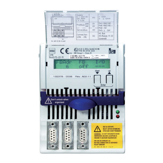
- Page 22 Parametrierung und Inbetriebnahme 9.1.2 StartUp Anzeige Einstellungen • Nach Anlegen der Hilfsenergie bootet das Gerät. FBAdr • Nach erfolgreichem Bootvorgang wechselt die LCD-Anzeige in die Systemebene (links dargestellt). 12258E00 9.1.3 Feldbusadresse einstellen Die Feldbusadresse kann nur eingestellt werden, wenn sich das Gerät nicht im Zustand Data Exchange befindet.
-
Page 23: Betrieb
Betrieb Betrieb 10.1 Betrieb Nach Montage, Installation und Inbetriebnahme (siehe Kapitel "Montage und Installation" und "Parametrierung und Inbetriebnahme") ist das CPU & Power Modul betriebsbereit. Weiterführende Dokumentation beachten (Kopplungsbeschreibung). 10.2 Anzeigen Entsprechende LEDs am Gerät zeigen den Betriebszustand des Geräts an (siehe auch Kapitel "Funktion und Geräteaufbau"). -
Page 24: Instandhaltung, Wartung, Reparatur
Instandhaltung, Wartung, Reparatur Wenn sich der Fehler mit den genannten Vorgehensweisen nicht beheben lässt: • An R. STAHL Schaltgeräte GmbH wenden. Zur schnellen Bearbeitung folgende Angaben bereithalten: • Typ und Seriennummer des Geräts • DCS/SPS • Protokoll • Revisions-Nr/Firmware-Version • Kaufdaten •... -
Page 25: Rücksendung
Reinigung 11.4 Rücksendung • Rücksendung bzw. Verpackung der Geräte nur in Absprache mit R. STAHL durchführen! Dazu mit der zuständigen Vertretung von R. STAHL Kontakt aufnehmen. Für die Rücksendung im Reparatur- bzw. Servicefall steht der Kundenservice von R. STAHL zur Verfügung. - Page 27 Operating instructions Additional languages r-stahl.com CPU & power module for Zone 2/Class I, Div. 2 Series 9440/15...
- Page 28 Contents Contents General Information .....................3 Manufacturer......................3 Information regarding the Operating Instructions..........3 Further Documents ....................3 Conformity with Standards and Regulations............3 Explanation of Symbols ..................4 Symbols used in these Operating Instructions.............4 Warning Notes .....................4 Symbols on the Device ..................5 Safety Notes ......................5 Operating Instructions Storage ................5 Personnel Qualification ..................5 Safe Use ......................6...
-
Page 29: En Fr
The original instructions are the German edition. They are legally binding in all legal affairs. Further Documents • IS1+ coupling description (download from r-stahl.com) • Data sheet • National information and documents relating to use in hazardous areas (see also chapter 1.4) For documents in other languages, see r-stahl.com. -
Page 30: Explanation Of Symbols
Explanation of Symbols Explanation of Symbols Symbols used in these Operating Instructions Symbol Meaning Tips and recommendations on the use of the device Explosive atmosphere hazard Warning Notes Warning notes must be observed under all circumstances, in order to minimise the risk resulting from design engineering and operation. -
Page 31: Symbols On The Device
Additional knowledge is required for any activity in hazardous areas. R. STAHL recommends having a level of knowledge equal to that described in the following standards: • IEC/EN 60079-14 (Electrical installations design, selection and erection) •... -
Page 32: Safe Use
• Use the device in accordance with its intended and approved purpose only. • Always consult R. STAHL Schaltgeräte GmbH if using the device under operating conditions which are not covered by the technical data. • Make sure that the device is not damaged. -
Page 33: Modifications And Alterations
Function and Device Design Commissioning, maintenance, repair • Only have commissioning and repairs performed by qualified and authorised persons (see chapter "Personnel qualification"). • Before commissioning, make sure that the device is not damaged. • Only perform the maintenance work described in these operating instructions. •... -
Page 34: Function
Function and Device Design Function The 9440/15 CPU & power module fulfils the function of a gateway between the internal bus of an IS1+ field station and the fieldbus which connects the field station singly or redundantly to the automation system. Application range The device is designed for IS1+ field stations and may be installed in hazardous areas of Zone 2/Class I, Div. -
Page 35: Technical Data
Technical Data Technical Data Explosion protection Global (IECEx) IECEx PTB 14.0039X Ex ec [ia Ga] [ib Gb] IIC T4 Gc Europe (ATEX, UKEX) PTB 99 ATEX 2222 E II 3 (2) G Ex ec [ia Ga] [ib Gb] IIC T4 Gc Certifications and certificates Certificates IECEx, ATEX, cFMus (Canada, USA), CCC (China), KTL (South Korea),... - Page 36 Technical Data Technical data Fieldbus, redundant fieldbus and service bus interfaces Interface RS485 Conductor length/ transfer rate Copper cable 1200 m at 9.6 to 93.75 kbps 1000 m at 187.5 kbps 400 m at 500 kbps 200 m at 1.5 Mbps Note FO technology is available for longer lengths Fibre optic...
- Page 37 Transmit diagnostics data (e.g. configuration error, hardware error, signal error) • Transmit HART commands from/to HART field devices Connectable • IS Wizard (using R. STAHL service bus) software packages • R. STAHL DTM • AMS from Emerson Process Management •...
- Page 38 (UL 94) Mounting/installation Installation conditions Mounting type on 35 mm DIN rail NS 35/15 Mounting horizontal and vertical orientation For further technical data, see r-stahl.com. CPU & power module 162278 / 9440609310 for Zone 2/Class I, Div. 2 2024-03-07·BA00·III·en·09 Series 9440/15...
-
Page 39: Project Engineering
Project Engineering Project Engineering NOTICE An ambient temperature that is too high may cause failure of the devices installed in the cabinet. Non-compliance can result in material damage. • Install and set up the cabinet in such a way that all devices installed within it are always operated within their permissible temperature range. -
Page 40: 7 Transport And Storage
Transport and Storage Transport and Storage • Transport and store the device only in the original packaging. • Store the device in a dry place (no condensation) free of vibrations. • Do not drop the device. Mounting and Installation The device is approved for use in gas hazardous areas of Zone 2, in dust hazardous areas of Zone 22 and in safe areas. -
Page 41: Mounting/Dismounting, Operating Position
Mounting and Installation Mounting/Dismounting, Operating Position 8.2.1 Mounting/Dismounting NOTICE Malfunction or device damage caused by improper mounting. Non-compliance may lead to material damage. • The device must only ever be mounted vertically, with the reading direction of the LCD display either from below, the left or the right. BusRail BusRail 12228E00... -
Page 42: Installation
Mounting and Installation 8.2.2 Requirements for Dismounting/Module Replacement Observe the following before dismounting or replacing the module: • Disconnect the auxiliary power. Dismounting • Loosen the screws of the pluggable terminal X5. • Disconnect pluggable terminal X5 from the module to be replaced. •... -
Page 43: Parameterisation And Commissioning
Parameterisation and Commissioning Parameterisation and Commissioning DANGER Explosion hazard due to incorrect installation! Non-compliance results in severe or fatal injuries. • Check the device for proper installation before commissioning. • Comply with national regulations. Before commissioning, ensure the following: • The device has been installed according to regulations. •... - Page 44 Parameterisation and Commissioning Display of the CPM status information LCD display Display/function Status and fieldbus address of the device. active FB addr : 12260E00 Type of coupling information Modbus V10-00 12264E00 Status of the device. status config/para fail Possible status information: 12265E00 Status information on the LCD display Meaning...
- Page 45 Parameterisation and Commissioning Display of the I/O module status information The following displays have the same structure for all I/O modules. LCD display Display/function Display of the slot, module type and module status. slot module OK/mode:0 Possible module statuses: 12268E00 Status information on the Meaning Priority...
- Page 46 Parameterisation and Commissioning Digital module In addition to the general displays, digital modules also have the following displays: LCD display Display/function In the absence of output data, the safety status of the outputs is displayed. slot (only for output modules) safety position 12272E00 I/O error.
- Page 47 Parameterisation and Commissioning Analogue module with HART The HART PVs can be displayed for HART module 9468. The submenu is only displayed if the analogue modules are configured to transmit HART PVs. Only configured HART PVs are displayed. LCD display Display/function Menu for displaying the HART PVs.
- Page 48 Parameterisation and Commissioning 9.1.2 Start-up Display Settings • After connecting the auxiliary power, the device will boot. FBAdr • After successful completion of the booting process, the LCD display switches to the system level (shown on the left). 12258E00 9.1.3 Setting the Fieldbus Address The fieldbus address can only be set if the device is not in Data Exchange mode.
-
Page 49: Operation
Operation Operation 10.1 Operation After mounting, installation and commissioning (see the "Mounting and installation" and "Parameterisation and commissioning" chapters) the CPU & power module is ready for operation. Please observe the additional documentation (coupling description). 10.2 Indicators The corresponding LEDs on the device indicate the operating state of the device (see also the "Function and device design"... -
Page 50: Maintenance, Overhaul, Repair
Maintenance, Overhaul, Repair If the error cannot be eliminated using the specified procedures: • Contact R. STAHL Schaltgeräte GmbH. For rapid processing, have the following information ready: • Type and serial number of the device • DCS/PLC • Protocol • Revision no./firmware version •... -
Page 51: Returning The Device
• Only return or package the devices after consulting R. STAHL! Contact the responsible representative from R. STAHL. R. STAHL's customer service is available to handle returns if repair or service is required. • Contact customer service personally. • Go to the r-stahl.com website. - Page 53 Class I, DIV 2 / Zone 2 Installation The Type 9440/15-01-11 CPU & Power Module is an nonincendive for connection to I/O Modules located in module for installation in Class I, Division 2, Group A-D or Class I, Class I, II, III, Division 2, Group A-G, Zone 2, Group IIC/IIB hazardous location;...
- Page 54 National Electrical Code, ANSI/NFPA 70 Article 500 or Canadian Electrical Code, CSA C22. Installation with the use of an appropriate fieldbus isolator for nonincendive fieldbus circuits (e.g. R. STAHL type 9185). The Ethernet interface is achieved with the use of media converters and switches providing optical Ethernet.
- Page 55 Block Diagram of an RS485 Field Station: I.S. Inputs and Outputs Class I, II, III, DIV 1, Groups A-G; Class I, Zone 0, IIC/IIB or Non I.S. or Nonincendive circuits, Class I, II, III, DIV 2, Group A-G; Class I, Zone 2, Group IIC/IIB Block Diagram of an Ethernet Field Station: I.S.
Need help?
Do you have a question about the 9440/15 Series and is the answer not in the manual?
Questions and answers