Chapters
Table of Contents

Related Manuals for Stahl 9415 Series


Summary of Contents for Stahl 9415 Series
- Page 1 Betriebsanleitung Additional languages www.r-stahl.com Diagnose Kommunikations Modul - Reihe 9415...
-
Page 2: Table Of Contents
Inhaltsverzeichnis Allgemeine Angaben ...................3 Hersteller ......................3 Angaben zur Betriebsanleitung ................3 Weitere Dokumente ....................3 Konformität zu Normen und Bestimmungen ............3 Erläuterung der Symbole ..................4 Symbole in der Betriebsanleitung ...............4 Warnhinweise .....................4 Symbole am Gerät ....................5 Sicherheitshinweise ....................5 Aufbewahrung der Betriebsanleitung ..............5 Qualifikation des Personals ................5 Sichere Verwendung ...................6 Umbauten und Änderungen ................7... -
Page 3: De De
Die Originalbetriebsanleitung ist die englische Ausgabe. Diese ist rechtsverbindlich in allen juristischen Angelegenheiten. Weitere Dokumente • Datenblatt Dokumente in weiteren Sprachen, siehe www.r-stahl.com. Konformität zu Normen und Bestimmungen Zertifikate und EU-Konformitätserklärung, siehe www.r-stahl.com. Das Gerät verfügt über eine IECEx-Zulassung. Zertifikat siehe IECEx-Homepage: http://iecex.iec.ch/... -
Page 4: Erläuterung Der Symbole
Erläuterung der Symbole Erläuterung der Symbole Symbole in der Betriebsanleitung Symbol Bedeutung Tipps und Empfehlungen zum Gebrauch des Geräts Gefahr durch explosionsfähige Atmosphäre Warnhinweise Warnhinweise unbedingt befolgen, um das konstruktive und durch den Betrieb bedingte Risiko zu minimieren. Die Warnhinweise sind wie folgt aufgebaut: •... -
Page 5: Symbole Am Gerät
Normen und Bestimmungen umfasst. Für Tätigkeiten in explosionsgefährdeten Bereichen sind weitere Kenntnisse erforderlich! R. STAHL empfiehlt einen Kenntnisstand, der in folgenden Normen beschrieben wird: • IEC/EN 60079-14 (Projektierung, Auswahl und Errichtung elektrischer Anlagen) • IEC/EN 60079-17 (Prüfung und Instandhaltung elektrischer Anlagen) •... -
Page 6: 3.3 Sichere Verwendung
• Bei Betriebsbedingungen, die durch die technischen Daten des Geräts nicht abgedeckt werden, unbedingt bei der R. STAHL Schaltgeräte GmbH rückfragen. • Sicherstellen, dass das Gerät unbeschädigt ist. • Für Schäden, die durch fehlerhaften oder unzulässigen Einsatz des Geräts sowie durch Nichtbeachtung dieser Betriebsanleitung entstehen, besteht keine Haftung. -
Page 7: Umbauten Und Änderungen
Funktion und Geräteaufbau Umbauten und Änderungen GEFAHR Explosionsgefahr durch Umbauten und Änderungen am Gerät! Nichtbeachten führt zu schweren oder tödlichen Verletzungen. • Gerät nicht umbauen oder verändern. Für Schäden, die durch Umbauten und Änderungen entstehen, besteht keine Haftung und keine Gewährleistung. Funktion und Geräteaufbau GEFAHR Explosionsgefahr durch zweckentfremdete Verwendung! -
Page 8: Geräteaufbau
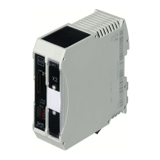
Feldbus-Segments ("SEG 1" ... "SEG 8", rot) (weitere Informationen siehe Kapitel "Anzeige") Schnittstelle RS-232 Schnittstelle "X2" für Firmware-Update (Zur Nutzung ausschließlich dem Servicepersonal der Firma R. STAHL Schaltgeräte GmbH oder 14713E00 unterwiesenem Personal des Betreibers vorbehalten.) Klemme FF H1 Anschlussklemme zur Übertragung der... - Page 9 Technische Daten Technische Daten Elektrische Daten Galvanische Trennung Feldbus zu 1500 V AC (Prüfspannung) Hilfsenergie Elektromagnetische Geprüft nach folgenden Normen und Vorschriften: Verträglichkeit EN 61326-1, IEC 61000-4-1 … 6 und 11, NAMUR NE 21 Elektrischer Anschluss Anschlussplan Host 1 Host 2 Host 4/8 Diagnosedaten Seg 1 (read) Diagnosedaten Seg 2 (read)
- Page 10 Technische Daten Technische Daten Gerätespezifische Daten Diagnose Schnittstelle Zum Anschluss ISbus Fieldbus Power Supplies 9412 (über bus-Träger 9419) Physical Layer durch Fieldbus Power Supplies 9412: Messungen (gem. Segment: Jitter, Signalpegel, Rauschen, Symmetrie, Strom und Spannung NAMUR NE 123) Feldgeräte: Jitter, Signalpegel Feldbus Schnittstelle Zum Anschluss Host und Asset Management Systeme mit H1 Schnittstelle...
-
Page 11: Projektierung
Montage / Installation Einbaubedingungen Einbaulage senkrecht oder waagrecht Montageart in bus-Träger Reihe 9419 Weitere technische Daten, siehe www.r-stahl.com. Projektierung HINWEIS Ausfall der installierten Geräte im Schaltschrank durch zu hohe Umgebungstemperatur! Nichtbeachten kann zu Sachschäden führen. • Schaltschrank so aufbauen und einrichten, dass er immer innerhalb des zulässigen Temperaturbereichs betrieben wird. -
Page 12: Transport Und Lagerung
Transport und Lagerung Transport und Lagerung • Gerät nur in Originalverpackung transportieren und lagern. • Gerät trocken (keine Betauung) und erschütterungsfrei lagern. • Gerät nicht stürzen. Montage und Installation Das Gerät ist für den Einsatz in gasexplosionsgefährdeten Bereichen der Zone 2 sowie im sicheren Bereich zugelassen. -
Page 13: Montage / Demontage, Gebrauchslage
Montage und Installation Montage / Demontage, Gebrauchslage 8.2.1 Montage Diagnose Kommunikations Modul - DCM auf bus-Träger 9419 Das Diagnose Kommunikations Modul - DCM wird auf den Montageplatz rechts von den Feldbus-Stromversorgungen auf den bus-Träger montiert. • Flachbandkabel zuerst am bus-Träger einstecken. •... -
Page 14: Installation
Montage und Installation Installation Bei Betrieb unter erschwerten Bedingungen wie insbesondere auf Schiffen sind zusätzliche Maßnahmen zur korrekten Installation je nach Einsatzort zu treffen. Weitere Informationen und Anweisungen hierzu erhalten Sie gerne auf Anfrage von Ihrem zuständigen Vertriebskontakt. 14715E00 Legende = Buchse bus-Träger = Verbindungskabel = Buchse X1... - Page 15 Montage und Installation Feldbusanschluss zur Übertragung der Diagnosedaten an den Host Host 1 Host 2 Host 4/8 Diagnosedaten Seg 1 (read) Diagnosedaten Seg 2 (read) Diagnosedaten Seg 4/8 (read) FPS 1 FPS 2 FPS 4/8 DCM 1 Diagnosedaten Seg 1...4/8 (send) Trunk 1 Trunk 2 Trunk 4/8...
-
Page 16: Parametrierung Und Inbetriebnahme
Parametrierung und Inbetriebnahme Anschluss an separates Diagnosesegment (optional) Host 2 Host 1 Host 4/8 Host D Diagnosedaten Seg 1 (read) Diagnosedaten Seg 2 (read) Diagnosedaten Seg 4/8 (read) FPS 1 FPS 2 FPS 4/8 DCM 1 FPS D Diagnosedaten Seg 1...4/8 (send) Trunk 1 Trunk 2 Trunk 4/8... -
Page 17: Anzeige
"SEG 4/8" erloschen Segment über Software deaktiviert Wenn sich der Fehler mit den genannten Vorgehensweisen nicht beheben lässt: • An R. STAHL Schaltgeräte GmbH wenden. Zur schnellen Bearbeitung folgende Angaben bereithalten: • Typ und Seriennummer des Geräts • Kaufdaten • Fehlerbeschreibung •... -
Page 18: Instandhaltung, Wartung, Reparatur
Die geltenden nationalen Bestimmungen im Einsatzland beachten. 11.3 Reparatur GEFAHR Explosionsgefahr durch unsachgemäße Reparatur! Nichtbeachten führt zu schweren oder tödlichen Verletzungen. • Reparaturen an den Geräten ausschließlich durch R. STAHL Schaltgeräte GmbH ausführen lassen. Diagnose Kommunikations Modul - DCM 209300 / 941560310010 Reihe 9415 2018-11-21·BA00·III·de·03... -
Page 19: Rücksendung
Reinigung 11.4 Rücksendung • Rücksendung bzw. Verpackung der Geräte nur in Absprache mit R. STAHL durchführen! Dazu mit der zuständigen Vertretung von R. STAHL Kontakt aufnehmen. Für die Rücksendung im Reparatur- bzw. Servicefall steht der Kundenservice von R. STAHL zur Verfügung. - Page 21 Operating instructions Additional languages www.r-stahl.com Diagnosis Communication Module - Series 9415...
- Page 22 Contents General Information ....................3 Manufacturer .......................3 Information regarding the Operating Instructions ..........3 Further Documents .....................3 Conformity with Standards and Regulations ............3 Explanation of the Symbols ................4 Symbols in these Operating Instructions ............4 Warning Notes ....................4 Symbols on the Device ..................5 Safety Notes .......................5 Operating Instructions Storage ................5 Personnel Qualification ..................5...
-
Page 23: En En
• Data sheet For documents in additional languages, see www.r-stahl.com. Conformity with Standards and Regulations See certificates and EU Declaration of Conformity: www.r-stahl.com. The device has IECEx approval. For certificate please refer to the IECEx homepage: http://iecex.iec.ch/ Further national certificates can be downloaded via the following link: https://r-stahl.com/en/global/products/support/downloads/. -
Page 24: Explanation Of The Symbols
Explanation of the Symbols Explanation of the Symbols Symbols in these Operating Instructions Symbol Meaning Tips and recommendations on the use of the device Danger due to explosive atmosphere Warning Notes Warnings must be observed under all circumstances, in order to minimize the risk due to construction and operation. -
Page 25: Symbols On The Device
Specialists who perform these tasks must have a level of knowledge that meets applicable national standards and regulations. Additional knowledge is required for tasks in hazardous areas! R. STAHL recommends having a level of knowledge equal to that described in the following standards: •... -
Page 26: 3.3 Safe Use
• Use the device in accordance with its intended and approved purpose only. • Always consult with R. STAHL Schaltgeräte GmbH if using the device under operating conditions which are not covered by the technical data. • Before installation, make sure that the device is not damaged. -
Page 27: Modifications And Alterations
Function and Device Design Modifications and Alterations DANGER Explosion hazard due to modifications and alterations to the device! Non-compliance results in severe or fatal injuries. • Do not modify or alter the device. No liability or warranty for damage resulting from modifications and alterations. -
Page 28: Device Design
("SEG 1" to "SEG 8", red) (for more information, see chapter "Indication") Interface "X2" RS-232 interface for firmware update (reserved for use exclusively by R. STAHL Schaltgeräte GmbH service 14713E00 personnel or trained personnel of the user.) Terminal FF H1 connection terminal for transmitting... - Page 29 Technical Data Technical Data Electrical data Galvanic separation Fieldbus to 1500 V AC (test voltage) Power Supply Electromagnetic Tested to the following standards and regulations: compatibility EN 61326-1, IEC 61000-4-1 to 61000-4-6, NAMUR NE 21 Electrical connection Connection diagram Host 1 Host 2 Host 4/8 Diagnosis data Seg 1 (read)
- Page 30 Technical Data Technical Data Device-specific data Diagnostics interface For connection to ISbus Fieldbus Power Supplies 9412 (via bus-Carrier 9419) Physical layer via Fieldbus Power Supplies 9412: measurement Segment: voltage / current, jitter, signal level, noise, balance, current and (acc. to voltage NAMUR NE 123) Fieldbus devices: jitter, signal level...
-
Page 31: Engineering
Mounting vertical or horizontal orientation Mounting type In Series 9419 bus-Carrier For further technical data, see www.r-stahl.com. Engineering NOTICE An ambient temperature that is too high may cause failure of the devices installed in the cabinet. Non-compliance can result in material damage. -
Page 32: Transport And Storage
Transport and Storage Transport and Storage • Transport and store the device only in the original packaging. • Store the device in a dry place (no condensation) and vibration-free. • Do not drop the device. Mounting and Installation The device is approved for use in hazardous areas of Zone 2 with potentially explosive gas as well as in safe areas. -
Page 33: Mounting / Dismounting, Operating Position
Mounting and Installation Mounting / Dismounting, Operating Position 8.2.1 Mounting a Diagnostics Communication Module - DCM on the 9419 bus-Carrier The diagnostics communication module - DCM is mounted in the mounting position of the bus-Carrier to the right of the fieldbus power supplies. •... -
Page 34: Installation
Mounting and Installation Installation Operation under difficult conditions, such as, in particular, on ships, requires additional measures to be taken for correct installation, depending on the place of use. Further information and instructions on this can be obtained from your regional sales contact on request. 14715E00 Legend = Bus-Carrier socket... - Page 35 Mounting and Installation Fieldbus connection for transmitting diagnostics data to the host Host 1 Host 2 Host 4/8 Diagnosis data Seg 1 (read) Diagnosis data Seg 2 (read) Diagnosis data Seg 4/8 (read) FPS 1 FPS 2 FPS 4/8 DCM 1 Diagnosis data Seg 1...4/8 (send) Trunk 1 Trunk 2...
-
Page 36: Parameterization And Commissioning
Parameterization and Commissioning Connection to separate diagnostics segment (optional) Host 2 Host 1 Host 4/8 Host D Diagnosis data Seg 1 (read) Diagnosis data Seg 2 (read) Diagnosis data Seg 4/8 (read) FPS 1 FPS 2 FPS 4/8 DCM 1 FPS D Diagnosis data Seg 1...4/8 (send) -
Page 37: Indication
LED goes out deactivated using the software If the error cannot be eliminated using the mentioned procedures: • Contact R. STAHL Schaltgeräte GmbH. For fast processing, have the following information ready: • Type and serial number of the device • Purchase information •... -
Page 38: Maintenance, Overhaul, Repair
DANGER Explosion hazard due to improper repair! Non-compliance results in severe or fatal injuries. • Repair work on the devices must be performed only by R. STAHL Schaltgeräte GmbH. Diagnosis Communication Module - DCM 209300 / 941560310010 Series 9415 2018-11-21·BA00·III·en·03... -
Page 39: Returning The Device
• Only return or package the devices after consulting R. STAHL! Contact the responsible representative from R. STAHL. R. STAHL's customer service is available to handle returns if repair or service is required. • Contact customer service personally. • Go to the www.r-stahl.com website. - Page 41 Do not disconnect Non-I.S. field wiring (X1 or X2) unless area is known to be non hazardous. Do not disconnect FF-H1 fieldbus connection if supplied from a source with voltage limited output per Ex ic (e.g. R. STAHL Type 9412/0*-3*0-1*) unless area is known to be non hazardous. Ambient temperature: -20°C … +70° C;...
Need help?
Do you have a question about the 9415 Series and is the answer not in the manual?
Questions and answers