Chapters
Table of Contents

Related Manuals for Stahl 9440/15 Series


Summary of Contents for Stahl 9440/15 Series
- Page 1 Betriebsanleitung Additional languages r-stahl.com CPU & Power Modul für Zone 2 / Div. 2 Reihe 9440/15...
-
Page 2: Table Of Contents
Inhaltsverzeichnis Allgemeine Angaben ...................3 Hersteller ......................3 Angaben zur Betriebsanleitung ................3 Weitere Dokumente ....................3 Konformität zu Normen und Bestimmungen ............3 Erläuterung der Symbole ..................4 Symbole in der Betriebsanleitung ...............4 Warnhinweise .....................4 Symbole am Gerät ....................5 Sicherheitshinweise ....................5 Aufbewahrung der Betriebsanleitung ..............5 Sichere Verwendung ...................5 Umbauten und Änderungen ................6 Funktion und Geräteaufbau ................6... -
Page 3: De De
• Installationsanleitung Schaltschrank • Datenblatt Weitere Sprachen, siehe r-stahl.com. Konformität zu Normen und Bestimmungen Siehe Zertifikate und EG-Konformitätserklärung: r-stahl.com. Das Gerät verfügt über eine IECEx-Zulassung. Siehe IECEx-Homepage: http://ie- cex.iec.ch/ Weitere nationale Zertifikate stehen unter dem folgenden Link zum Download bereit: http://r-stahl.com/downloads/certificates.html. -
Page 4: Erläuterung Der Symbole
Erläuterung der Symbole Erläuterung der Symbole Symbole in der Betriebsanleitung Symbol Bedeutung Tipps und Empfehlungen zum Gebrauch des Geräts Gefahr durch explosionsfähige Atmosphäre Gefahr durch spannungsführende Teile Warnhinweise Warnhinweise unbedingt befolgen, um das konstruktive und durch den Betrieb bedingte Risiko zu minimieren. Die Warnhinweise sind wie folgt aufgebaut: •... -
Page 5: Symbole Am Gerät
• Bei Betriebsbedingungen, die von den technischen Daten abweichen, unbedingt bei der R. STAHL Schaltgeräte GmbH rückfragen. • Das CPU & Power-Modul 9440/15 ist für den Einsatz in explosionsgefährdeten Bereichen der Zone 2 und Zone 22 sowie im sicheren Bereich zugelassen. -
Page 6: 3.3 Umbauten Und Änderungen
Funktion und Geräteaufbau Umbauten und Änderungen GEFAHR Explosionsgefahr durch Umbauten und Änderungen am Gerät! Nichtbeachten führt zu schweren oder tödlichen Verletzungen. • Gerät nicht umbauen oder verändern. Für Schäden, die durch Umbauten und Änderungen entstehen, besteht keine Haftung und keine Gewährleistung. Funktion und Geräteaufbau GEFAHR Explosionsgefahr durch zweckentfremdete Verwendung! -
Page 7: Geräteaufbau
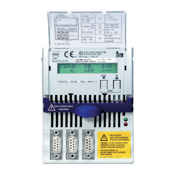
Funktion und Geräteaufbau Geräteaufbau Gerätelement Beschreibung Abdeckklappe Abdeckklappe mit Einlegeschild (geöffnet) LCD-Anzeige Anzeige von Diagnosedaten, Eingangs- und Ausgangswerten Beschriftung Angaben zum Modul (Seriennummer, Hardware-Revisionsnummer, Software-Revisions- nummer, Herstelldatum, z. B.: 123456DE9999 Rev.A 01-01 0508) 7 8 9 Tasten Tasten <up>, <down> 12226E00 Rasthebel Rasthebel zum Entfernen des Moduls von der... -
Page 8: 5 Technische Daten
Technische Daten Technische Daten Explosionsschutz Global (IECEx) IECEx PTB 14.0039 Ex nA [ia, ib Gb] IIC T4 Gc Europa (ATEX) PTB 99 ATEX 2222 E II 3 (2) G Ex nA [ia, ib Gb] IIC T4 Gc Bescheinigungen und Zertifikate Bescheinigungen IECEx, ATEX, Brasilien (INMETRO), Kanada (CSA), Kasachstan (TR), Russland (TR), USA (FM), Weißrussland (TR), Kanada (FM) - Page 9 Ausgänge lesen und schreiben • Diagnosedaten übertragen (z.B. Konfig-Fehler, Hardware-Fehler, Signal-Fehler) • HART-Kommandos von / zu HART-Feldgeräten übertragen Anschließbare • IS Wizard (über R. STAHL ServiceBus) Softwarepakete • R. STAHL DTM • AMS von Emerson Process Management • PDM von Siemens •...
- Page 10 Module IP30 Anschlüsse IP20 Montage / Installation Einbaubedingungen Montageart auf 35 mm DIN-Schiene NS 35/15 Einbaulage waagrecht und senkrecht Weitere technische Daten, siehe r-stahl.com. CPU & Power Modul für Zone 2 / Div. 2 162278 / 9440609310 Reihe 9440/15 2019-01-10·BA00·III·de·07...
-
Page 11: Projektierung
Projektierung Projektierung GEFAHR Explosionsgefahr durch Geräteausfall durch zu hohe Umgebungstemperatur im Schaltschrank! Nichtbeachten führt zu schweren oder tödlichen Verletzungen. • Schaltschrank so aufbauen und einrichten, dass jederzeit Betrieb im zulässigen Temperaturbereich möglich ist (Lüftung). • "Installationsanleitung Schaltschrank" sorgfältig beachten. Bei der Projektierung folgende Bedingungen beachten: •... -
Page 12: Montage Und Installation
Montage und Installation Montage und Installation GEFAHR Explosionsgefahr bei fehlendem Gehäuse! Nichtbeachten führt zu schweren oder tödlichen Verletzungen. • Gerät in explosionsgefährdeten Bereichen (Zone 2 oder 22) unbedingt in ein Gehäuse einbauen. • Sicherstellen, dass das Gehäuse die Anforderungen der IEC/EN 60079-15 oder IEC/EN 60079-31 erfüllt. -
Page 13: Montage / Demontage, Gebrauchslage
Montage und Installation Montage / Demontage, Gebrauchslage Bei Betrieb unter erschwerten Bedingungen wie insbesondere auf Schiffen, sind zusätzliche Maßnahmen zur korrekten Installation je nach Einsatzort zu treffen. Weitere Informationen und Anweisungen hierzu erhalten Sie gerne auf Anfrage von Ihrem zuständigen Vertriebskontakt. •... -
Page 14: Installation
Parametrierung und Inbetriebnahme Installation GEFAHR Explosionsgefahr durch Stecken oder Trennen von Anschlussleitungen im Betrieb! Nichtbeachten führt zu schweren oder tödlichen Verletzungen. • Vor dem Einstecken und Ausstecken der Hilfsenergie oder Sub-D-Stecker das Gerät spannungsfrei schalten. 8.3.1 Hilfsenergie anschließen • Die Hilfsenergie an der Klemme X5 anschließen (siehe Kapitel "Steckbare Klemme X5") •... -
Page 15: Parametrierungen
Parametrierung und Inbetriebnahme Parametrierungen Die Parametrierung und Inbetriebnahme des CPM und der angeschlossenen I/O-Module erfolgt über das Automatisierungssystem und den ServiceBus (optional). Nur die Feldbusadresse des CPM muss direkt am Modul eingestellt werden. Über die LCD-Anzeige mit Tasten lassen sich •... -
Page 16: 10 Betrieb
Betrieb Nach dem Einstellen der Feldbusadresse bootet das Gerät erneut. Die Feldbusadresse ist permanent gespeichert und steht auch nach einem Reset oder einer Wiederinbetriebnahme zur Verfügung. Betrieb 10.1 Betrieb Nach Montage, Installation und Inbetriebnahme (siehe Kapitel "Montage und Installation" und "Parametrierung und Inbetriebnahme") ist das CPU & Power-Modul betriebsbereit. Weiterführende Dokumentation beachten (Kopplungsbeschreibung). - Page 17 Betrieb Anzeige Status-Informationen der CPM LCD-Anzeige Anzeige/Funktion Zustand und Feldbus-Adresse des Geräts. active FB addr : 12260E00 Kopplungsart information Modbus V10-00 12264E00 Status des Geräts. status config/para fail 12265E00 Mögliche Status-Informationen: Status-Information in Bedeutung LCD-Anzeige no error kein Fehler hardware fail (1) Hardwarefehler gefunden hardware fail (2) falsche Hardware-Kennung...
- Page 18 Betrieb Anzeige Status-Informationen der Input / Output Module Die folgenden Anzeigen sind für alle Input/Output-Module gleich aufgebaut. LCD-Anzeige Anzeige/Funktion Anzeige des Steckplatzes, des Modultyps und des Modulzustands. slot module OK/mode:0 12268E00 Mögliche Modulzustände: Status-Information in Bedeutung Prio LCD-Anzeige IOM no response Kommunikation mit dem Modul ist nicht möglich.
- Page 19 Betrieb Digital Module Zusätzlich zu den allgemeinen Anzeigen gibt es bei Digital Modulen noch folgende Anzeigen: LCD-Anzeige Anzeige/Funktion Ohne Ausgabedaten wird Sicherheitszustand der Ausgänge slot angezeigt. safety position 12272E00 (nur bei Output Module) IO-Fehler. slot : Drahtbruch 12273E00 : Kurzschluss IO-Daten und -Fehler.
- Page 20 Betrieb Analog-Module mit HART Für das HART-Module 9468 können die HART PV dargestellt werden. Das Untermenü erscheint nur, wenn die Analog-Module für die Übertragung von HART PV konfiguriert sind. Es werden nur die konfigurierten HART PV angezeigt. LCD-Anzeige Anzeige/Funktion Menü zur Anzeige der HART PV. slot Aufruf der Untermenüs durch gleichzeitiges Drücken von ▲...
-
Page 21: Fehlerbeseitigung
• CPM richtig auf BusRail aufrasten. • CPM tauschen. Wenn sich der Fehler mit den genannten Vorgehensweisen nicht beheben lässt: • An R. STAHL Schaltgeräte GmbH wenden. Zur schnellen Bearbeitung folgende Angaben bereithalten: • Typ und Seriennummer • Kaufdaten • Fehlerbeschreibung •... -
Page 22: 11 Instandhaltung, Wartung, Reparatur
11.3 Reparatur GEFAHR Explosionsgefahr durch unsachgemäße Reparatur! Nichtbeachten führt zu schweren oder tödlichen Verletzungen. • Reparaturen an den Geräten ausschließlich durch R. STAHL Schaltgeräte GmbH ausführen lassen. 11.4 Rücksendung Für die Rücksendung im Reparatur-/Servicefall das Formular "Serviceschein" verwenden. Auf der Internetseite "r-stahl.com" im Menü "Downloads >... -
Page 23: Entsorgung
Zubehör und Ersatzteile HINWEIS Fehlfunktion oder Geräteschaden durch den Einsatz nicht originaler Bauteile. Nichtbeachten kann Sachschaden verursachen! • Nur Original-Zubehör und Original-Ersatzteile der R. STAHL Schaltgeräte GmbH verwenden. Zubehör und Ersatzteile, siehe Datenblatt auf Homepage r-stahl.com. 162278 / 9440609310 CPU & Power Modul für Zone 2 / Div. 2 2019-01-10·BA00·III·de·07... - Page 24 Operating instructions Additional languages r-stahl.com CPU & Power Module for Zone 2 / Div. 2 Series 9440/15...
- Page 25 Contents General Information ....................3 Manufacturer .......................3 Information regarding the operating instructions ..........3 Further documents ....................3 Conformity with standards and regulations ............3 Explanation of the symbols .................4 Symbols in these operating instructions .............4 Warning notes .....................4 Symbols on the device ..................5 Safety notes ......................5 Operating instructions storage ................5 Safe use ......................5...
-
Page 26: En En
• Data sheet For further languages, see r-stahl.com. Conformity with standards and regulations See certificates and EC Declaration of Conformity: r-stahl.com. The device has IECEx approval. See IECEx homepage: http://iecex.iec.ch/ Further national certificates can be downloaded via the following link: http://r-stahl.com/downloads/certificates.html. -
Page 27: Explanation Of The Symbols
Explanation of the symbols Explanation of the symbols Symbols in these operating instructions Symbol Meaning Tips and recommendations on the use of the device Danger due to explosive atmosphere Danger due to live components Warning notes Warning notes must be observed under all circumstances, in order to minimize the risk due to construction and operation. -
Page 28: Symbols On The Device
• Always consult with R. STAHL Schaltgeräte GmbH in case of operating conditions which deviate from the technical data. • The CPU & Power Module 9440/15 is approved for use in hazardous areas of Zone 2 and Zone 22 and in safe areas. -
Page 29: 3.3 Modifications And Alterations
Function and device design Modifications and alterations DANGER Explosion hazard due to modifications and alterations to the device! Non-compliance results in severe or fatal injuries. • Do not modify or alter the device. No liability or warranty for damage resulting from modifications and alterations. -
Page 30: Device Design
Function and device design Device design Device component Description Cover flap Cover flap with symbol label (open) LCD display For display of diagnostic data, input and output values Labelling Module data (serial number, hardware revision number, software revision number, date of manufacture, e.g.: 123456DE9999 Rev.A 01-01 0508) 7 8 9 Buttons... - Page 31 Technical data Technical data Explosion Protection Global (IECEx) IECEx PTB 14.0039 Ex nA [ia, ib Gb] IIC T4 Gc Europe (ATEX) PTB 99 ATEX 2222 E II 3 (2) G Ex nA [ia, ib Gb] IIC T4 Gc Certifications and certificates Certificates IECEx, ATEX, Brazil (INMETRO), Canada (CSA), Kazakhstan (TR), Russia (TR), USA (FM), Belarus (TR), Canada (FM)
- Page 32 Read and write outputs • Transfer diagnostic (e.g. config. error, hardware error, signal error) • Transfer HART commands to/from HART field devices. Connectable software • IS Wizard (via R. STAHL ServiceBus) packages • R. STAHL DTM • AMS by Emerson Process Management •...
-
Page 33: Technical Data
Mounting / Installation Installation conditions Mounting type on 35 mm DIN rail NS 35/15 Mounting orientation horizontal and vertical For further technical data, see r-stahl.com. CPU & Power Module for Zone 2 / Div. 2 162278 / 9440609310 Series 9440/15 2019-01-10·BA00·III·en·07... -
Page 34: Engineering
Engineering Engineering DANGER Explosion hazard due to device failure caused by a high ambient temperature in the cabinet! Non-compliance results in severe or fatal injuries. • Design and set up the cabinet such that operation in the permissible temperature range is possible at any time (ventilation). •... -
Page 35: Mounting And Installation
Mounting and installation Mounting and installation DANGER Explosion hazard if enclosure is missing! Non-compliance results in severe or fatal injuries. • In hazardous areas (Zone 2 or 22), the device must be installed in an enclosure. • Make sure that the enclosure fulfils the requirements of IEC/EN 60079-15 or IEC/EN 60079-31. -
Page 36: Mounting / Dismounting, Operating Position
Mounting and installation Mounting / dismounting, operating position Operation under difficult conditions, such as, in particular, on ships, requires additional measures to be taken for correct installation, depending on the place of use. Further information and instructions on this can be obtained from your regional sales contact on request. -
Page 37: Installation
Parameterization and commissioning Installation DANGER Explosion hazard when plugging in or disconnecting connecting cables during operation! Non-compliance results in severe or fatal injuries. • Before plugging in or unplugging the auxiliary power or Sub-D connector, the device must be de-energized. 8.3.1 Connection of the auxiliary power •... -
Page 38: Parameterizations
Parameterization and commissioning Parameterizations Parameterization and commissioning of the CPM and of the connected I/O modules is carried out using the automation system and the ServiceBus (optional). Only the fieldbus address of the CPM must be set directly at the module. The buttons of the LCD display can be used •... -
Page 39: 10 Operation
Operation After setting the fieldbus address, the device boots again. The fieldbus address is permanently saved and is also available after reset or recommissioning. Operation 10.1 Operation After mounting, installation and commissioning (see chapter "Mounting and installation" and "Parameterization and commissioning") the CPU & Power Module is ready for operation. - Page 40 Operation Display of the CPM status information LCD display Display/function Status and fieldbus address of the device active FB addr : 12260E00 Type of coupling information Modbus V10-00 12264E00 Status of the device. status config/para fail 12265E00 Possible status information: Status information on the LCD Meaning display...
- Page 41 Operation Displaying status information of the input / output modules The following displays show the same design for all output/input modules. LCD display Display/function Display of the slot, module type and module status. slot module OK/mode:0 12268E00 Possible module statuses: Status information on Meaning Prio...
- Page 42 Operation Digital modules In addition to the general displays, digital modules also exhibit the following displays: LCD display Display/function In the absence of output data, the safety status of the outputs is slot displayed. safety position 12272E00 (for output module only) IO error.
- Page 43 Operation Analog Modules HART For HART Module 9468, the HART PV can be displayed. The submenu appears only if the Analog Modules have been configured for HART PV transmission. Only configured HART PVs are displayed. LCD display Display/function Menu for displaying the HART PV. slot To display the submenu, press ▲...
-
Page 44: Troubleshooting
• Engage the CPM correctly on the BusRail. • Replace CPM. If the error cannot be eliminated using the mentioned procedures: • Contact R. STAHL Schaltgeräte GmbH. For fast processing, have the following information ready: • Type and serial number • Purchase information •... -
Page 45: 11 Maintenance And Repair
On the internet site "r-stahl.com" under "Downloads > Customer service": • Download the service form and fill it out. • Send the device along with the service form in the original packaging to R. STAHL Schaltgeräte GmbH. CPU & Power Module for Zone 2 / Div. 2... -
Page 46: Disposal
Malfunction or damage to the device due to the use of non-original components. Non-compliance can result in material damage. • Use only original accessories and spare parts from R. STAHL Schaltgeräte GmbH. For accessories and spare parts, see data sheet on our homepage r-stahl.com. - Page 48 Class I, DIV 2 / Zone 2 Installation The Type 9440/15-01-11 CPU & Power Module is an nonincendive for connection to I/O Modules located in module for installation in Class I, Division 2, Group A-D or Class I, Class I, II, III, Division 2, Group A-G, Zone 2, Group IIC/IIB hazardous location;...
- Page 49 National Electrical Code, ANSI/NFPA 70 Article 500 or Canadian Electrical Code, CSA C22. Installation with the use of an appropriate fieldbus isolator for nonincendive fieldbus circuits (e.g. R. STAHL type 9185). The Ethernet interface is achieved with the use of media converters and switches providing optical Ethernet.
- Page 50 Block Diagram of an RS485 Field Station: I.S. Inputs and Outputs Class I, II, III, DIV 1, Groups A-G; Class I, Zone 0, IIC/IIB or Non I.S. or Nonincendive circuits, Class I, II, III, DIV 2, Group A-G; Class I, Zone 2, Group IIC/IIB Block Diagram of an Ethernet Field Station: I.S.
Need help?
Do you have a question about the 9440/15 Series and is the answer not in the manual?
Questions and answers