
Related Manuals for Stahl ISpac 9174 Series


Summary of Contents for Stahl ISpac 9174 Series
- Page 1 Manual Additional languages r-stahl.com Electronic relay module Series 9174...
-
Page 2: Table Of Contents
Contents General Information ....................3 Manufacturer .......................3 About these Manual ....................3 Further Documents .....................3 Conformity with Standards and Regulations ............3 Explanation of the Symbols ................4 Symbols in this Manual ..................4 Symbols on the Device ..................4 Safety ........................5 Intended Use .......................5 Personnel Qualification ..................5 Residual Risks ....................6 Transport and Storage ..................7 Product Selection and Project Engineering ............8... -
Page 3: En En
Make the manual accessible to operating and maintenance personnel at all times. Pass the manual on to each subsequent owner or user of the device. Update the manual every time you receive an amendment to it from R. STAHL. ID-No.:... -
Page 4: Explanation Of The Symbols
Explanation of the Symbols Explanation of the Symbols Symbols in this Manual Symbol Meaning Tip for making work easier DANGER! Dangerous situation which can result in fatal or severe injuries causing permanent damage if the safety measures are not complied with. WARNING! Dangerous situation which can result in severe injuries if the safety measures are not complied with. -
Page 5: Safety
Specialists who perform these tasks must have a level of knowledge that meets applicable national standards and regulations. Additional knowledge is required for tasks in hazardous areas! R. STAHL recommends having a level of knowledge equal to that described in the following standards: •... -
Page 6: 3.3 Residual Risks
(see the "Technical data" chapter). Do not place any load on the device. Check the packaging and the device for damage. Report any damage to R. STAHL immediately. Do not commission a damaged device. Store the device in its original packaging in a dry place (with no condensation), and make sure that it is stable and protected against the effects of vibrations and knocks. -
Page 7: Transport And Storage
Transport and Storage Improper mounting, installation, commissioning, maintenance or cleaning Basic work such as installation, commissioning, maintenance or cleaning of the device must be performed only in accordance with the valid national regulations of the country of use and only by qualified persons. Otherwise the explosion protection can be rendered ineffective. -
Page 8: Product Selection And Project Engineering
3 mH Typical values: 0.6 mH/km. Ask the cable manufacturer for the exact specification. Additional circuitry with a freewheeling diode is recommended. R. STAHL offers compatiable accessories from Series 8453 (e.g. 145169 article number, SB 550 encapsulated diode for installation in Zone 1 or 2). - Page 9 5.000 5.000 5.000 Additional circuitry with a freewheeling diode is recommended. R. STAHL offers compatiable accessories from Series 8453 (e.g. 145169 article number, SB 550 encapsulated diode for installation in Zone 1 or 2). Maximum switching frequency based on the capacitive load Capacitive 30 μF...
-
Page 10: Mounting And Installation
Mounting and Installation Mounting and Installation Mounting / Dismounting Mount the device carefully and only in accordance with the safety notes (see Chapter "Safety"). Read through the following installation conditions and assembly instructions carefully and follow them precisely. 6.1.1 Mounting / Dismounting on Top Hat Rail Mounting Only mount the device on DIN rails that correspond to IEC/EN 60715. -
Page 11: Installation
Mounting and Installation Installation Operation under difficult conditions, in particular on ships, requires additional measures to be taken for correct installation, depending on the operating location. Further information and instructions on this can be obtained from your regional sales contact upon request. 6.2.1 Ex i Connection (Terminal 3, 4) DANGER! Explosion hazard due to exposed or incorrectly installed conductors at the Ex i terminal! -
Page 12: Commissioning
LED remains off If the error cannot be eliminated using the specified procedures: Contact R. STAHL Schaltgeräte GmbH. For rapid processing, have the following information ready: • Type and serial number of the device • Purchase information •... -
Page 13: Maintenance, Overhaul, Repair
Only return or package the devices after consulting R. STAHL! Contact the responsible representative from R. STAHL. R. STAHL's customer service is available to handle returns if repair or service is required. Contact customer service personally. Go to the r-stahl.com website. -
Page 14: Cleaning
Accessories and Spare Parts NOTICE! Malfunction or damage to the device due to the use of non-original components. Non-compliance can result in material damage. Use only original accessories and spare parts from R. STAHL Schaltgeräte GmbH (see data sheet). Electronic relay module... -
Page 15: Annex A
Annex A Annex A 14.1 Technical Data Explosion Protection Global (IECEx) Gas and dust IECEx BVS 17.0050X Ex eb mb [ib Gb] IIC T4 Gb [Ex ib Db] IIIC Europe (ATEX) Gas and dust BVS 17 ATEX E 057 X E II 2 G Ex eb mb [ib Gb] IIC T4 Gb E II (2) D [Ex ib Db] IIIC Certifications and certificates... - Page 16 Annex A Technical Data Electrical data Galvanic separation acc. to standard EN 60079-11 Input to output 1500 V AC Auxiliary power none Max. power 1.42 W dissipation Ex i input Switching level for ON / OFF 14 to 28 V Note Switching level = output voltage of binary output - internal resistance of binary output x 15 mA ≥...
- Page 17 DIN rail (NS35/15, NS35/7.5) Mounting orientation horizontal or vertical Degree of protection Enclosure IP40 Terminals 3,4 IP20 (Ex i) Terminals 5,6 IP30 (Ex e) Enclosure material polyamide 6GF For further technical data, see r-stahl.com. 917460330020 Electronic relay module 2019-05-13·HB00·III·en·03 Series 9174...
-
Page 18: Annex B
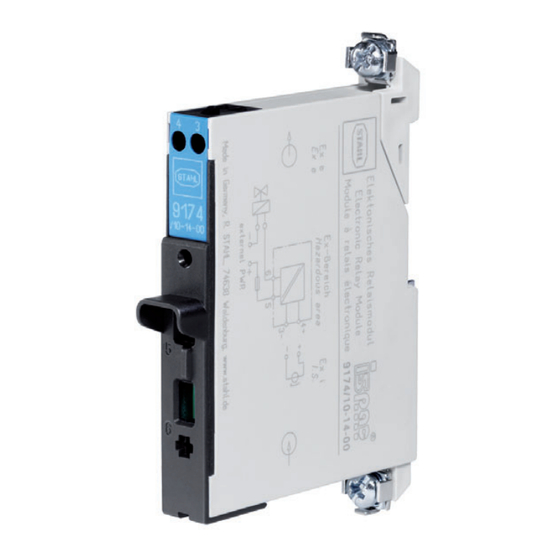
Annex B Annex B 15.1 Device Design Device component Description Screw terminal Non-functional Blue terminals 3, 4 Ex i connection terminals for connecting the intrinsically safe control system Yellow LED Indication of the switching state Black terminals 5, 6 Ex e connection terminals for connecting the load to be switched Screw terminal Non-functional...
Need help?
Do you have a question about the ISpac 9174 Series and is the answer not in the manual?
Questions and answers