Table of Contents
Advertisement
Quick Links
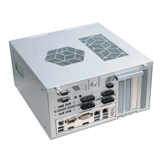
GM831-CSF Installation Guide
• One GM831-CSF system unit
• Demonstration kit:
- Power Supply (PSU)
Note:
The software package that came with the system contains application and code samples
to implement gaming software for the system.
DFI reserves the right to change the specifications at any time prior to the product's release. For the
latest revision and details of the installation process, please refer to the user's manual.
Package Contents
www.dfi.com
1
Advertisement
Table of Contents

Related Manuals for DFI GM831-CSF


Summary of Contents for DFI GM831-CSF
- Page 1 The software package that came with the system contains application and code samples to implement gaming software for the system. DFI reserves the right to change the specifications at any time prior to the product's release. For the latest revision and details of the installation process, please refer to the user's manual.
-
Page 2: Ports And Connectors
Ports and Connectors DVI-D Intrusion Switch COM 3~4 USB 2.0 COM 1 PS/2, KB/ HDMI DP++ Line-out USB 3.1 USB 3.1 Mic-in Expension Slots Gen 1 Gen 2 Front View Front View (with Power Supply) -
Page 3: Connecting The Power Supply
Connecting the Power Supply The PSU is an optional item of GM831-CSF for the power supply solution. The instruction below is to demonstrate the process to connect the PSU to GM831-CSF. Make sure the system and all other peripherals connected to it have been powered off. - Page 4 Installing a 2.5" SATA Drive Mounting screws (step screws) SATA Drive Mounting screw HDD Bracket...
- Page 6 Installing GM901 GM901...
- Page 7 PCIe x1 Door 7 Door 8 COM 1 PCIe x1 PCIe x1...
-
Page 8: Board Layout And Jumper Settings
Fan 3 USB 7-8 (CS331-C246 only) or Optional SATA 3.0 Vertical USB 9 USB 2.0 Clear CMOS Data Mini PCIe/mSATA Signal Select Normal (default) 1-2 On Mini PCIE (default) 1-2 On Clear CMOS Data 2-3 On mSATA 2-3 On www.dfi.com... - Page 9 Selection for COM 1 JP1/JP2 Selection for COM 2 JP6/JP8 RS232 1-3, 2-4 On RS232 1-3, 2-4 On RS422 3-5, 4-6 On RS422 3-5, 4-6 On RS485 3-5, 4-6 On RS485 3-5, 4-6 On Selection for COM 1 Selection for COM 2 JP10 RS232 1-3, 4-6 On...
-
Page 10: Connector Pin Assignment
Connector Pin Assignment COM1/COM2 RS232/422/485 Select Pins RS232 RS422 RS485 DCD- DATA+ SIN- DATA- DTR- 1 2 3 4 5 DSR- RTS- 6 7 8 9 CTS- COM1/COM2 RS232 Power Select Pins RS232 RS232 with power DCD- +12V SIN- SIN- DTR- DTR- DSR-... - Page 11 COM 3/4: RS232 Front Panel Pin Assignment Pins Assignment Pins Assignment Pins Pin Assignment N.C. LED Power DCD- PWR- HDD Power LED Power SIN- Signal Signal Ground Ground ATX- DTR- RESET Signal Signal N.C. DSR- RTS- CTS- USB 3.1 Gen 2 5-6 Header USB 2.0 7-8/9-10 Headers Pins Assignment...
-
Page 12: Digital I/O Connector
Digital I/O Connector CPU Fan Pins Pin Assignment Pins Pin Assignment Pins Pin Assignment +12V DIO7 +12V +12V DIO6 Sense DIO5 Speed Control DIO4 System Fan 1/2/3 DIO3 DIO2 +5VDU Pins Pin Assignment DIO1 +5VDU DIO0 Power Sense LAN LED Pin Assignment SATA 3.0 0/1/2/3/5 /6 (CS331~C246 only) Pins... -
Page 13: Chassis Intrusion
+12V Power S/PDIF Pins Pin Assignment Pins Assignment Pins Assignment +12V +12V SPDIF out +12V +12V SPDIF in ATX Power Chassis Intrusion Pins Pin Assignment Pins Pin Assignment +3.3V +3.3V Pins Pin Assignment +3.3V -12V Signal PS_ON# PWR_OK +5VSB +12V +12V +3.3V SMBus...
Need help?
Do you have a question about the GM831-CSF and is the answer not in the manual?
Questions and answers