
Related Manuals for Parker UTS-ID


Summary of Contents for Parker UTS-ID
- Page 1 Effective: August 2021 Supersedes: UTS-ID User Manual Universal Tilt Sensor for Impact Detection...
- Page 2 Offer of Sale The items described in this document are hereby offered for sale by Parker Hannifin Corporation, its subsidiaries or its authorized distributors. This offer and its acceptance are governed by the provisions stated in the "Offer of Sale"...
- Page 3 Publication History The following table provides an overview of the changes made to this document over the course of its publication history Revision Description of Change Rev. 001 First release of this document Parker Hannifin Corporation – UTS User Manual...
-
Page 4: Table Of Contents
Connector ....................................11 Mounting Requirements ................................12 CAN Information ................................13 SAE J1939 ....................................13 Identifier Description ................................13 UTS Communications ................................13 Protocol Defaults ..................................14 Table 7.4.1: Default Product Messages and Setup........................14 Parker Hannifin Corporation – UTS User Manual... - Page 5 Table 7.4.2: Data Broadcast Message (Orientation and Acceleration) ..................15 Table 7.4.3: SAE J1939 Standard Messages Received by UTS-ID ..................... 16 Table 7.4.4: SAE J1939 Standard Messages transmitted by UTS-ID ..................17 Table 7.4.5: Configuration Messages (Parameter Change) ..................... 19 Table 7.4.6: Configuration Messages (Save) ..........................
- Page 6 Table 7.5.7: Query Messages Received by UTS........................17 Table 7.5.8: Reply Messages Transmitted by UTS ........................ 18 Table 8.1.1: CAN Extended Identifier Example ........................19 Table 8.5.1: Example Information Data Frame ........................22 Parker Hannifin Corporation – UTS User Manual...
-
Page 7: Safety
Contact the manufacturer if there is anything you are not sure about or if you have any questions regarding the product and its handling or maintenance. The term "manufacturer" refers to Parker Hannifin Corporation. Safety Symbols The following symbols are used in this document to indicate potentially hazardous situations: Danger! Risk of death or injury. -
Page 8: Publication History
Before performing any work on the hydraulics control electronics, ensure that The machine cannot start moving Functions are positioned safely The machine is turned off The hydraulic system is relieved from any pressure Supply voltage to the control electronics is disconnected Parker Hannifin Corporation – UTS User Manual... -
Page 9: Document Introduction
Table 2.2.1: Abbreviation List Abbreviation Explanation UTS-ID Universal Tilt Sensor – Impact Detection Controller Area Network Electromagnetic Interference Society of Automotive Engineers Parameter Group Number MEMS Micro Electro-Mechanical Systems Finite Impulse Response Infinite Impulse Response Parker Hannifin Corporation – UTS User Manual... -
Page 10: Datasheet
0.488 mG/bit ISO 11452-2 100 V/m ISO 7637-2 and -3 transients ISO 10605:2008 ±15 kV Shock 1m drop Mechanical Vibration 40 Gs Climate Sealing IP68/IP69K (with rear connector protection) Chemical Liquids (resistance) standard automotive Parker Hannifin Corporation – UTS User Manual... -
Page 11: Table Of Figures
• Data broadcast rate 0.1 Hz • Data broadcast rate 0.1 Hz • Refer to part drawing for CAN • Refer to ES-043 for CAN message specification message specification Figure 4.1.1: UTS Quick Sheet Page 1 Parker Hannifin Corporation – UTS User Manual... -
Page 12: Figure 4.1.2: Uts Quick Sheet
Figure 4.1.2: UTS Quick Sheet Page 2 Parker Hannifin Corporation – UTS User Manual... -
Page 13: Product Introduction
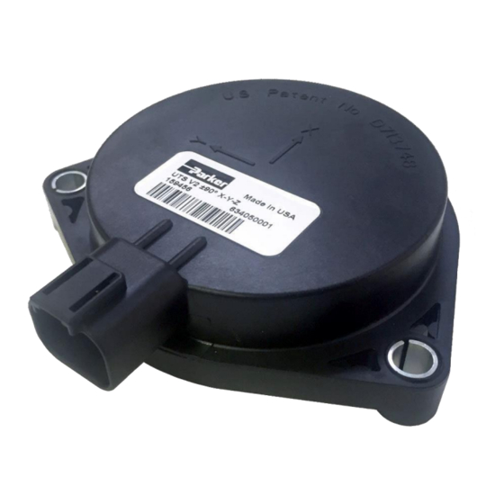
The UTS-ID accelerometers are used to calculate changes in orientation with respect to gravity to compute and communicate impact events. The sensor communicates over CAN bus using SAE J1939 protocol and has an integral Deutsch connector. UTS-ID is IoT ready and can be integrated with Parker Mobile IoT solutions. -
Page 14: Uts Filtering Description
UTS Filtering Description The UTS-ID has a two stage filtering operation – where the user has some customization opportunity in the second stage. Stage 1 – Kalman Filter The first stage, a Kalman Filter, is responsible for tracking the orientation of the sensor by combing the accelerometer and gyro readings. -
Page 15: Stage 2 - User Configurable Exponential Low Pass Filter
– 4.8 ms. (variable is in seconds, so use 0.0048 s for calculations. Characteristically, the larger the value of Lambda, the less aggressive the filter. Similarly, the lower value selected for Lambda, the longer it will take to response. Parker Hannifin Corporation – UTS-ID User Manual... -
Page 16: Plotting Stage 2 Filter Responses
It should be noted that: The left Y axis label represents the x(n) signal (impulse function) magnitude. The right Y axis label represents the y(n) signal response of x(n) after passing through the filter. Parker Hannifin Corporation – UTS-ID User Manual... -
Page 17: Installation Guidelines
For a list of the default settings of the UTS refer to Table 7.4.1. Power Supply Requirements Table 6.3.1 shows the power supply requirements for the UTS-ID. The UTS-ID operates in 12V or 24V systems and can operate from 6 V to 36 V with a regulated voltage supply. -
Page 18: Mounting Requirements
Avoid mounting to metal less than 1/8” (3.175mm) thick as this can cause excess vibration. Mounting Orientation The sensor output is agnostic to mounting orientation. Mount the sensor with regards to the desired sealing capacity noted in Section 5.1 – Reliability. Parker Hannifin Corporation – UTS-ID User Manual... -
Page 19: Can Information
CAN network. The UTS-ID uses this protocol to transmit its condition as a predefined set of outputs. All messages are SAE J1939 Proprietary B PGN's except the address claim request and response. -
Page 20: Protocol Defaults
2 bytes Direction Z (Unit Vector) 0x7FFF 16-bit Int unit/bit 1) Once an impact is detected no further impacts messages will be sent out until the debounce time has passed (2.000 seconds by default). Parker Hannifin Corporation – UTS-ID User Manual... - Page 21 Measured x-axis acceleration Acceleration X bit Int g/bit Unsigned 16- 4.88289e-4 2 bytes Measured y-axis acceleration Acceleration Y bit Int g/bit Unsigned 16- 4.88289e-4 2 bytes Measured z-axis acceleration Acceleration Z bit Int g/bit Parker Hannifin Corporation – UTS-ID User Manual...
- Page 22 2) The request message may be sent to a specific address (0-253) or the global destination address (255) 3) The UTS-ID will respond to a request message for Address Claimed (directed to its Source Address or the global address) with a successful Address Claimed (AC) message before resuming other transmissions;...
- Page 23 Industry Group SPN 2846, set in Group 0, parameter number 24 in Table 7.4.7 bits Arbitrary Address Capable SPN 2844, 0 – UTS-ID is not set to perform Address Arbitration, cannot be changed Parker Hannifin Corporation – UTS-ID User Manual...
- Page 24 1 bit Arbitrary Address SPN 2844, 0 – UTS-ID is not set to perform Address Arbitration, cannot be changed Capable 6) Upon power-up, only the Cannot Claim Address message can be transmitted until an address is successfully claimed with the Address Claimed message 7) Transmitted once at startup.
- Page 25 9) Received by the UTS-ID Application for reading and changing configuration parameters. 10) Transmitted by the UTS-ID Application in response to a read/write request. 11) After receiving a valid read message, the UTS-ID will send a response message with the Destination Address (DA) set to the Source Address of the requestor...
- Page 26 Table 7.4.6: Configuration Messages (Save) Save Configuration Changes Message Parameter Group Definition 0xEF00 (61184) PDU2 Format Data Length Parameter Name Format Byte 1 byte Command Byte 0xC1 7 bytes Unused Bytes 0xFFFFFFFFFF Parker Hannifin Corporation – UTS-ID User Manual...
- Page 27 Unsigned Integer 12) If the Source Address is changed with a write message, the UTS-ID must respond with a successful Address Claimed (AC) message before resuming other transmissions; otherwise, the Cannot Claim Address message must be sent and the UTS-ID...
-
Page 28: This Table Has To Do With The Production Process And Is Purposfully Left Blank
Table 7.4.8: Configuration Parameter Numbers (Group 1) This table has to do with the production process and is purposfully left blank. Production process – Group 1 Group Parameter UTS-ID Length Format Default Number Number Capable Configuration Parameter Parker Hannifin Corporation – UTS-ID User Manual... - Page 29 13 (0x0D) Gyros Transmission Interval R/Wm 4 bytes Unsigned Long 0xFFAE 14 (0x0E) Raw Accel PGN R/Wm 4 bytes Unsigned Long 0xFFFF FFFF 15 (0x0F) Raw Accel Transmission R/Wm 4 bytes Unsigned Long Interval Parker Hannifin Corporation – UTS-ID User Manual...
-
Page 30: Application Examples/How Do I
Final Value value 8204 Direction of X (unit vector) 33284 3.05180e-5 unit/bit 0.01576 7D28 Direction of Y (unit vector) 32040 3.05180e-5 unit/bit -0.022203 FFF2 Direction of Z (unit vector) 65522 3.05180e-5 unit/bit 0.9996 Parker Hannifin Corporation – UTS-ID User Manual... - Page 31 Description Value Resolution Offset Final Value value 0047 2.44144e-4 g/bit 0.017334 Magnitude 7FFF Acceleration X 32767 4.88289e-4 g/bit -0.000234 8000 Acceleration Y 32768 4.88289e-4 g/bit 0.000253 8023 Acceleration Z 32803 4.88289e-4 g/bit 0.017344 Parker Hannifin Corporation – UTS-ID User Manual...
-
Page 32: Configuration Messages
0x02 (Read Response) request 1 byte Parameter Group Number 0x00 1 byte Parameter ID Number 0x00 4 bytes Parameter Value 0x04 0x00 0x00 0x00 (Returns “Revision Number” from the Group 0 – configuration set Parker Hannifin Corporation – UTS-ID User Manual... -
Page 33: On Demand Messages
SPN 2846, set in Group 0, 0 (3 bits) parameter number 24 in Table 7.4.7 1 bit Arbitrary Address SPN 2844, 0 – UTS-ID is not set 0 (1 bit) Capable to perform Address Arbitration, cannot be changed Parker Hannifin Corporation – UTS-ID User Manual... -
Page 34: Transmitting A Command
Address Claim: 18EEFFE3 00 00 E0 08 00 88 00 30 Note: Regular message start broadcasting at this time. Notes: • The UTS source address is changed immediately after receiving the save configuration message. Parker Hannifin Corporation – UTS-ID User Manual... -
Page 35: Change The Pgn Of The Impact
01 C1 01 00 FF FF FF FF Notes: • Valid values for the PGN of the output data frame are 0x0000 to 0xFFFE • When an impact is triggered the sensor would broadcast a message with the id: 0x18FF05E4 Parker Hannifin Corporation – UTS-ID User Manual... -
Page 36: Adjust The Internal Filtering Of The Uts-Id
Adjust the internal filtering of the UTS-ID Process Steps 1. Calculate how aggressive to make the filter. 2. Adjust the paremeter to the closest filter setting desired (must be between 0 and 1) 3. Save configuration settings. EXAMPLE – ADJUSTING EXPONENTIAL DECAY FILTER (UTS SOURCE ADDRESS = 0XE4) 1. - Page 37 Event Timeout and makes a decision if an impact has been created based on the settings that directly affect the input into the evaluation logic. This will impact the response time of the sensor. Parker Hannifin Corporation – UTS-ID User Manual...
- Page 38 Fig. 7 shows what the Impact Threshold does to detect an algorithm. Note that x(n) is the original signal being detected, and y(n) is the filter response inside the UTS-ID. This shows what would be deemed an acceptable filter setting if the minimum threshold was 3 g. As you can see with the Filter decay rate, the first impact would not trigger, but the second impact with the higher magnitude would trigger a response from the sensor.
- Page 39 Figure 8: How variance is Visualized The UTS-ID incudes an option to change the tolerable variane of the signal. Variance is different from standard deviation in that Variance is the average of the squared differences from the mean, while standard devication is the squarte root of the variance.
- Page 40 Figure 9: Putting it Together - Filtering with the UTS-ID Fig. 9 shows a few things; x(n), y(n), and Varriance Value (VV). Some of the numbers look like they would be close so the data has been converted to a table as well.
- Page 41 0.32 4.23 0.23 3.84 -0.13 1.25 -0.36 -0.02 -0.18 0.34 0.02 1.50 0.09 0.71 -0.13 0.41 -0.07 0.52 -0.03 -0.5 0.34 -0.06 0.37 0.01 -0.3 0.25 -0.02 0.22 -0.02 0.19 0.00 0.15 -0.01 Parker Hannifin Corporation – UTS-ID User Manual...
-
Page 42: Instructions
6. Send ID 0x18EFE4F9, Send Save config message – Data bytes: C1 00 00 00 00 00 00 00 UTS responds with ID 0x18EFF9E4 (acknowledge) – Data bytes: 01 C1 01 00 FF FF FF FF Parker Hannifin Corporation – UTS-ID User Manual... -
Page 43: Performance Considerations
This is also an opportunity to test what the desired threshold and attenuation for the impact detection is. Using multiple sensors on the same CAN bus system Each UTS will need to have a unique source address. Parker Hannifin Corporation – UTS-ID User Manual... -
Page 44: Uts - Id Integration With Parker Iot
10.1 UTS-ID Sensor integration with IoT solutions UTS-ID impact sensor can be integrated as an option to the Parker Mobile IoT solution. The impact sensor Canbus data can be configured to integrate data with controller or Parker Mobile IoT gateway. -
Page 45: Signal Visualization
Parker Mobile IoT widgets that will include Line, Bar, Text and other widget types. 10.4 Impact Alerting and Notifications Parker Mobile IoT user can setup alert and notification thresholds in different states including critical, warning or just for information. Use the impact signals from the sensor like magnitude, acceleration or orientation and set specific values to trigger alerts. -
Page 46: Impact Reports
10.5 Impact Reports Impact reports are obtained from the Parker Mobile IoT portal. Impact reports populated based on impact events gathered from the sensor, along with location and time data. Impact reports include 11 FAQ The FAQ for UTS can be found at http://blog.parker.com/faqs... - Page 47 Parker Hannifin Corporation Electro Mechanical and Controls Division 850 Arthur Avenue Elk Grove Village, IL 60007 phone 800 221 9257...
Need help?
Do you have a question about the UTS-ID and is the answer not in the manual?
Questions and answers