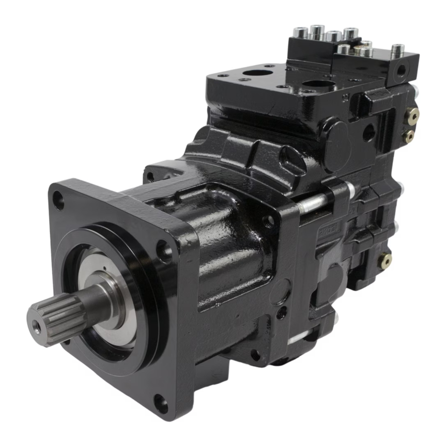
Parker F11 / F12 / V12 / V4 / T12 Series Manual
- Service and spare parts instruction (42 pages) ,
- Service spare parts list (40 pages) ,
- Service manual (16 pages)
Advertisement
Visit our homepage for additional support parker.com/pmde
GENERAL INFORMATION
The sensor consists of a ferrostat differential (Dual Channel) speed sensor and a seal nut. The sensor installs in a threaded hole in the F12, V12, V14 or T12 bearing housing, and in the F11 barrel housing. The sensor output is a 2 phase shifted square wave signal within a frequency rang of 0 Hz to 15 kHz. The sensor detects both speed and direction of rotation. The sensor withstands high as well as low temperatures and is highly moisture protected (IP68).
| Frame Size | No. of pulses/rev. |
| F11-6, -10, -12, -14, -19 | 5 |
| F12 (30-125) | 35 |
| F12 (152-182) | 40 |
| F12-250 Up to serial no. 201602230409 | 64 |
| F12-250 From serial no. 201602230410 | 36 |
| V12/V14 (ISO, SAE and Cartridge) | 36 |
| T12-060 and V12 -060 Cartridge | 9 |
TECHNICAL DATA
| Power supply | 10V to 30V protected against reverse polarity. |
| Current consumption | Max 20 mA. (without load) |
| Signal output |
|
 NOTE: The outputs are short circuit proof and protected against reverse polarity.
| Frequency | Min 0 Hz max 15 kHz |
| Insulation | Housing and electronics galvanically separated (500V/50Hz/1 min) |
| Operating temperature | -40 to +125°C [-40 to +255°F] |
| Protection class | IP68 (DIN 40050) |

| Sensor head pressure | Max 25 bar [360 psi] |
| Weight (incl. cable) | 0.15 kg [0.33 lb] |
| Sensing distance | 0.1 to 2.0 mm; 1.0 recom. [0.004 to 0.08 in; 0.04 recom.] |
| Transistor | NPN |
| Amplifier variant | Variant; .02 SHW Output 1: Speed Output 2: Speed Output type: Open Col. |
| CABLE | |
| Material | PUR casting |
| Length | 1.0 m |
| No. of wires | 4 (plus screen; transparent) Wire area 4 x 0.34 mm² |
| Screen | Stranded metal net (insulated from housing) |
NOTE: Screen must be connected to 0 V (zero volt) power supply.
Bending radius Min 25 mm [1 in]
CONNECTION
Sensor wires are susceptible to radiated noise.
Therefore, the following should be noted:
- Uninterrupted screened 4 wire cable must be used and the screen only connected to the appropriate instrument screen input terminal or 0V. Connections to power earth are not advisable.
- The sensor wires must be installed as far away as possible from electrical machines and must not run in parallel with power cables in the vicinity.
The maximum cable length that can be utilized is dependent on sensor voltage, how the cable is installed, and cable capacitance and inductance. It is, however, always advantageous to keep the distance as short as possible. The sensor cable supplied can be lengthened via a terminal box located in an IP20 protected connection area (per DIN 40050).
Contact Pump & Motor Division Europe for recommendations.
Connections and Pulse Diagram:
Direction of rotation

INSTALLATION INFORMATION
As the sensor has a built-in differential Hall effect device, the sensor housing must be aligned according to the drawing (Fig. 1& 2) of the Speed Sensor Installation picture. If it is not, the sensor may not function properly and noise immunity decreases. The sensor is non-sensitive to oil and the stainless steel housing withstands hazardous environment conditions.

Speed sensor installation, F12, V12,V14, T12

INSTALLATION PROCEDURE
- Install the sensor in the threaded hole (M12x1) of the F12/V12/V14/T12 bearing housing; turn the sensor until its head just touches the ring gear teeth (F12) or the shaft head (F12-250/V12/V14/ T12); refer to the installation drawing above.
- On *F11 the pistons positions must be known before mounting the sensor. Install the sensor in the threaded hole (M12x1) of the F11 barrel housing; turn the sensor until its head just touches the piston.
- When mounting the sensor in the threaded hole, be sure that you also rotate the cable so the cable not get twisted.
- Back off the sensor one turn (counter clockwise).
- If required, back it off further until the sensor guiding hole centerline is as shown in Fig. 1 & 2 or 180° opposite.
- Tighten the seal nut; max 12 Nm (100 lb in). Be sure that the position of the guiding hole centerline still is correct.
- Connect the electrical wires as shown in the schematic. Please note the instructions regarding screening.
- If you only use one signal, we recommend you to use S2 cable. Cut S1 cable and isolate.
- F11: -6, -10, -12. -14, -19
Position notification regarding Machinery Directive 2006/42/EG:
Products made by the Pump & Motor Division Europe (PMDE) of Parker are excluded from the scope of the machinery directive following the "Cetop" Position Paper on the implementation of the Machinery Directive 2006/ 42/ EC in the Fluid Power Industry.
All PMDE products are designed and manufactured considering the basic as well as the proven safety principles according to:
- SS EN ISO13849-2:2008-09, C.2 and C.3 and,
- SS EN 982+A1:2008,
so that the machines in which the products are incorporated meet the essential health and safety requirements.
Confirmations for components to be proven component, e. g. for validation of hydraulic systems, can only be provided after an analysis of the specific application, as the fact to be a proven component mainly depends on the specific application.
Dr. Hans Haas General Manager
Pump & Motor Division Europe
|
This document and other information from Parker Corporation, its subsidiaries and authorized distributors provide product or system options for further investigation by users having technical expertise. The user, through its own analysis and testing, is solely responsible for making the final selection of the system and components and assuring that all performance, endurance, maintenance, safety and warning requirements of the application are met. The user must analyze all aspects of the application, follow applicable industry standards, and follow the information concerning the product in the current product catalog and in any other materials provided from Parker or its subsidiaries or authorized distributors. To the extent that Parker or its subsidiaries or authorized distributors provide component or system options based upon data or specifications provided by the user, the user is responsible for determining that such data and specifications are suitable and sufficient for all applications and reasonably foreseeable uses of the components or systems. |

Parker Hannifin Manufacturing, Sweden AB
Pump & Motor Division Europe
461 82 Trollhättan
Sweden
Tel. +46 (0)520 40 45 00
www.parker.com/pmde
Documents / ResourcesDownload manual
Here you can download full pdf version of manual, it may contain additional safety instructions, warranty information, FCC rules, etc.
Advertisement


Need help?
Do you have a question about the F11 Series and is the answer not in the manual?
Questions and answers