Table of Contents
Advertisement
Quick Links
Advertisement
Table of Contents

Related Manuals for Parker GS100


Summary of Contents for Parker GS100
- Page 1 Effective: June 2020 Supercedes: GS100 User Manual J1939 CAN Speed Sensor...
- Page 2 Offer of Sale The items described in this document are hereby offered for sale by Parker Hannifin Corporation, its subsidiaries or its authorized distributors. This offer and its acceptance are governed by the provisions stated in the "Offer of Sale"...
- Page 3 Publication History The following table provides an overview of the changes made to this document over the course of its publication history Revision Description of Change Rev. 001 First release of this document Parker Hannifin Corporation – GS100 User Manual...
-
Page 4: Table Of Contents
Identifier Description ..........................16 Data field structure ..........................17 Communication Message Types ......................17 Adjustable User Parameters ......................... 17 Transmitted Messages ......................... 18 Request and Response Messages ...................... 21 Sensor Configuration Messages ......................24 Parker Hannifin Corporation – GS100 User Manual... - Page 5 Configuring Source Address using CAN Command ................28 FAQ ................................28 Table of Figures Figure 4.3.1 GS100 Dimensions .......................... 11 Figure 4.4.1 GS100 Pin Position (DTM04-6P) ..................... 11 Figure 5.1.1 GS100 Functional Block Diagram ....................12 Table of Tables Table 2.2:1 Abbreviation List ..........................7 Table 4.4:1 GS100 Pinout ............................
-
Page 6: Safety
Contact the manufacturer if there is anything you are not sure about or if you have any questions regarding the product and its handling or maintenance. The term "manufacturer" refers to Parker Hannifin Corporation. Safety Symbols The following symbols are used in this document to indicate potentially hazardous situations. -
Page 7: Welding After Installation
Before performing any work on the hydraulics control electronics, ensure that: The machine cannot start moving Functions are positioned safely The machine is turned off The hydraulic system is relieved from any pressure Supply voltage to the control electronics is disconnected Parker Hannifin Corporation – GS100 User Manual... -
Page 8: Document Introduction
The purpose of this document is to detail performance characteristics, installation recommendations, and define CAN messages for the GS100 Sensor product. These Instructions/guidelines are to be used as a reference tool for the manufacturer’s design, production, and service personnel. The user of this manual should have basic knowledge in the handling of electronic equipment. -
Page 9: Product Information
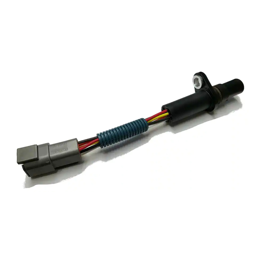
Product Information Overview The GS100 sensor belongs to the Parker family of gear speed sensors which can measure speed and direction of a ferrous gear based on principles of Hall-effect technology. This sensor broadcasts the measured data over a CAN bus using SAE J1939 protocol. OEMs can customization multiple CAN parameters like baud rate, message frequency rate, and source address which provides easy tuning of the sensor according to the application need. -
Page 10: Sensor Specifications
External Pull-Up cc-Pullup Recommended Pull-Up Voltage 0.01 Operational Frequency µs Output signal Rise Time µs Output signal Fall Time 3.45 3.69 3.95 Output signal High Voltage (sink) 0.45 0.95 Output signal Low Voltage (sink) Parker Hannifin Corporation – GS100 User Manual... -
Page 11: Product Features
ISO 7637-2 2004 Pulse 5a, +87V peak 400ms duration Climate IP67 and IP69K rated Chemical Liquids (resistance) standard automotive Certifications EU RoHS 2 CE EN61000-6-2, EN61000-6-4, EN 13309, ISO 13766-1, ISO13766-2, ISO 14982 Parker Hannifin Corporation – GS100 User Manual... -
Page 12: Product Dimensions
Product Dimensions Figure 4.3.1 GS100 Dimensions Connector Pinout The GS100 utilizes the Deutsch DTM04-6P connector. See below for pinout definitions: Figure 4.4.1 GS100 Pin Position (DTM04-6P) Terminal / Pin Description Wire Color Supply Voltage Ground Black Speed Open Drain Output... -
Page 13: Product Usage
Product Usage Functional Block Diagram Figure 5.1.1 GS100 Functional Block Diagram Parker Hannifin Corporation – GS100 User Manual... -
Page 14: Address Resistor Selection Guide
Resistor Value [Ω] Source Address <294 0x80 0x81 0x82 1.5k 0x83 2.3k 0x84 3.32k 0x85 5.36k 0x86 9.53k 0x87 >10k Source Address retrieved from Flash Memory 0x80 Table 5.2:1 Resistor Source Address Selector Parker Hannifin Corporation – GS100 User Manual... -
Page 15: Installation Guidelines
The O-ring seal in GS100 sensor is intended for tank pressure applications, typically of 5 psi or less. Fluid pressure above this limit risks damage to the sensor and fluid leaks. Customer shall verify the performance of the sensor and O-ring seal subjected to application pressures. - Page 16 Air gap is one of the vital requirements to this sensor to operate normally and to measure the target gear’s speed and direction accurately. It varies from target to target, contact Parker Engineering for optimum airgap before installing the sensor in the application. Failing to mount the sensor within the optimized airgap range, would cause incorrect output information and may not give output at all.
-
Page 17: Can Information
CAN network. The GS100 uses this protocol to transmit its condition as a predefined set of outputs. All messages are SAE J1939 Proprietary B PGN's except the address claim request and response. -
Page 18: Data Field Structure
Specific Address Message: This is the “Command mode” message for the sensor. In these messages the GS100 receives write and query messages to its node address from the J1939 bus. Ensure there is no loss of power while making programming changes with the GS100 in service... -
Page 19: Transmitted Messages
Checksum = Byte1 + Byte2 + Byte3 + Byte4 + Byte5 + Byte6 + Byte7 + Message Counter & 0x0F + Message ID Low Byte + Message ID Mid Low Byte + Message ID Mid High Byte + Message ID High Byte Message Checksum = (((Checksum >> 6) & 0x03) + (Checksum >> 3) + Checksum) & 0x07. Parker Hannifin Corporation – GS100 User Manual... - Page 20 3 bits Industry Group SPN 2846, Industry Group is 0. SPN 2844, 0 – Speed Sensor is not capable of selecting alternate Source Address 1 bit Arbitrary Address Capable itself, cannot be changed Parker Hannifin Corporation – GS100 User Manual...
- Page 21 The 19-bit Suspect Parameter Number is used to identify the item for which diagnostics are being reported. The 7-bit Occurrence Count field contains the number of times a fault has been independently detected. The occurrence count will not be incremented from 126 to 127. Parker Hannifin Corporation – GS100 User Manual...
-
Page 22: Request And Response Messages
The request message may be sent to the specific Source address (0-253) or the Global destination address (255). The GS100 will respond to a request message for Address Claimed with a successful Address Claimed (AC) message before resuming other transmissions;... - Page 23 SPN 586, Not used, replace with ASCII ‘*’ delimiter. 0 bytes Make 7 bytes Model SPN 587, 7 ASCII characters, Parker SAP part number. 7 bytes Serial Number SPN 588, 7 ASCII characters, identity number from NAME, set by parameter number 001.
- Page 24 Unsigned Integer, message function for version number request. Value is 0x13 1 byte Request type 4 bytes Part Number Unsigned Integer, 953604- Speed Sensor application, 953612- Speed Sensor bootloader. (LSB byte first MSB byte last). 1 byte Reserved 0xFF Parker Hannifin Corporation – GS100 User Manual...
-
Page 25: Sensor Configuration Messages
When sending a read/write message the Destination Address (DA) will be the Source Address of the Speed Sensor receiving the message. Some examples for the configuration parameters read/write messages can be found at the end of the document. Parker Hannifin Corporation – GS100 User Manual... - Page 26 Resistor input modified during running will not change the source address or store the value in flash. When source address is modified using CA message, it will update during runtime and stores in flash. If the source address value changed using CAN message is out of range, Speed Sensor will ignore the request. Parker Hannifin Corporation – GS100 User Manual...
-
Page 27: Application Examples/How Do I
Parameter Number Sensor) Example - Write Configuration Parameter, Moving Average Filter Sample Size Identifier 18EFF980 0x81 0x0A DA = 0x80(Speed Command Configuration Write Reserved Bytes Sensor) Type Parameter Number Operation Data SA = 0xF9 Parker Hannifin Corporation – GS100 User Manual... -
Page 28: Read/Write Example For Sensor's Broadcast Status Message Pgn
SA = 0x80(Speed Sensor) Type Parameter Number Example - Write configuration parameter, CAN Baud Rate Identifier 18EFF980 0x81 DA = 0x80(Speed Sensor) Command Configuration Write Reserved Bytes SA = 0xF9 Type Parameter Operation Data Number Parker Hannifin Corporation – GS100 User Manual... -
Page 29: Configuring Source Address Using Can Command
– 1byte. Total message includes 9 bytes of information. Connection management for Transport protocol BAM message as per J1939-21 standard. Packet Number. The FAQ for GS100 can be found at http://blog.parker.com/faqs for additional product support. Parker Hannifin Corporation – GS100 User Manual... - Page 30 © 2020 Parker Hannifin Corporation. All rights reserved. MSG33-2383-UM 06/20 Parker Hannifin Corporation Electronic Controls Division 850 Arthur Avenue Elk Grove Village, IL 60007 phone 800 221 9257 www.parker.com...
Need help?
Do you have a question about the GS100 and is the answer not in the manual?
Questions and answers