Table of Contents
Advertisement
Advertisement
Table of Contents

Related Manuals for Parker 162703ECD


Summary of Contents for Parker 162703ECD
- Page 1 Effective: June 2019 Supersedes:...
- Page 2 Offer of Sale The items described in this document are hereby offered for sale by Parker Hannifin Corporation, its subsidiaries or its authorized distributors. This offer and its acceptance are governed by the provisions stated in the "Offer of Sale"...
- Page 3 The following table provides an overview of the changes made to this document over the course of its publication history Revision Description of Change Rev. 001 First release of this document Rev. 002 Formatting updates Parker Hannifin Corporation – UTS User Manual...
-
Page 4: Table Of Contents
Transmitting a command ............................19 Change the UTS source address ..........................19 Change the PGN of the output data frame ......................20 Adjust the zero-tilt reading (offset) of the output data ..................21 Parker Hannifin Corporation – UTS User Manual... - Page 5 Table 7.5.7: Query Messages Received by UTS ........................17 Table 7.5.8: Reply Messages Transmitted by UTS ........................ 18 Table 8.1.1: CAN Extended Identifier Example ........................19 Table 8.5.1: Example Information Data Frame ........................22 Parker Hannifin Corporation – UTS User Manual...
-
Page 6: Safety
Contact the manufacturer if there is anything you are not sure about or if you have any questions regarding the product and its handling or maintenance. The term "manufacturer" refers to Parker Hannifin Corporation. Safety Symbols The following symbols are used in this document to indicate potentially hazardous situations: Danger! Risk of death or injury. -
Page 7: Construction Regulations
Before performing any work on the hydraulics control electronics, ensure that The machine cannot start moving Functions are positioned safely The machine is turned off The hydraulic system is relieved from any pressure Supply voltage to the control electronics is disconnected Parker Hannifin Corporation – UTS User Manual... -
Page 8: Document Introduction
The abbreviations and acronyms used in this manual are defined in the following table. Table 2.2.1: Abbreviation List Abbreviation Explanation Universal Tilt Sensor Controller Area Network Electromagnetic Interference Society of Automotive Engineers Parameter Group Number MEMS Micro Electro-Mechanical Systems Finite Impulse Response Infinite Impulse Response Parker Hannifin Corporation – UTS User Manual... -
Page 9: Datasheet
ISO 11452-2 100 V/m ISO 7637-2 and -3 transients ISO 10605:2008 ±15 kV Shock 1m drop Mechanical Vibration 40 Gs Climate Sealing IP68/IP69K (with rear connector protection) Chemical Liquids (resistance) standard automotive Parker Hannifin Corporation – UTS User Manual... -
Page 10: Installation Quick Sheets
4 Installation Quick Sheets UTS Version 2 Figure 4.1.1: UTS Quick Sheet Page 1 Parker Hannifin Corporation – UTS User Manual... -
Page 11: Figure 4.1.2: Uts Quick Sheet
Figure 4.1.2: UTS Quick Sheet Page 2 Parker Hannifin Corporation – UTS User Manual... -
Page 12: Product Introduction
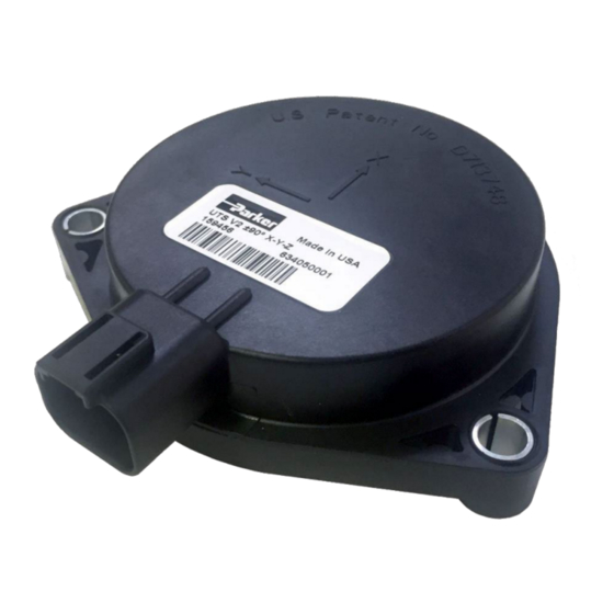
2 or 3 axis’. All options have three mounting holes in a tripod pattern to facilitate level installation and a 4- pin sealed Deutsch DT connector type designed for automotive use. These features provide for easy installation and removal, even in field conditions. Figure 5.1.1: UTS with Deutsch DT04-4P Connector Parker Hannifin Corporation – UTS User Manual... -
Page 13: Uts Filtering Description
Setting the heavy IIR rate limit to the max value of 983.025 °/s (0xFFFF) disables the heavy IIR filter. Setting the FIR samples to 1 and the IIR filter weight percent to 100% yields an unfiltered output. • Parker Hannifin Corporation – UTS User Manual... -
Page 14: Installation Guidelines
Transients See ISO 7637-2,-3 Connector The UTS uses the Deutsch DT series connector type. Technical details are listed below. Mating Connector: DT06-4S 1062-16-0144 Figure 6.4.1: UTS Mating Connector Figure 6.4.2: UTS Connector Diagram Parker Hannifin Corporation – UTS User Manual... -
Page 15: Mounting Requirements
If the device is not level after installation, coordinate offsets can be made to account for this. Refer to Section 8.3 for an example on how to adjust offsets. Parker Hannifin Corporation – UTS User Manual... -
Page 16: Can Information
Specific Address Message: This is the “Service mode” message for the sensor. In these messages the UTS receives write and query messages to its node address from the J1939 bus. Ensure there is no loss of power while making programming changes with the UTS in service mode Parker Hannifin Corporation – UTS User Manual... -
Page 17: Protocol Defaults
Power to Broadcast Delay 110 ms (typ.) Note: If the cells are not split up into three identifying sections, then the cell applies to all three sensors. *Settling times will fluctuate if filtering settings are changed Parker Hannifin Corporation – UTS User Manual... -
Page 18: Can Message Specification Tables
0xEA (Address claim) UTS source address, valid range: 0x00 to 0xFE, must 1 byte PGN (PS) match the destination address in the PGN Note: Data length in this message is expected to be 3 bytes Parker Hannifin Corporation – UTS User Manual... -
Page 19: Table 7.5.2: General Acknowledge Message
8-bit unsigned integer, valid range: 0x00 to 0xFE, 1 byte address 0xFE = NULL address New source 8-bit unsigned integer, valid range: 0x00 to 0xFE, 1 byte address 0xFE = NULL address 6 bytes Reserved Parker Hannifin Corporation – UTS User Manual... -
Page 20: Table 7.5.5: Write Messages Received By Uts 2 - Configure Pgn, Set Offset, Subscribe To Information
1 = subscribe to information frame, other = unsubscribe 1 byte Subscription from information frame Information 8-bit unsigned integer, 10ms per bit with 0ms offset, 20ms 1 byte broadcast minimum interval 5 bytes Reserved Parker Hannifin Corporation – UTS User Manual... -
Page 21: Table 7.5.6: Write Messages Received By Uts 3 - Output Filter, Apply Configuration
The UTS can have multiple commands sent to it while in service mode. An, “apply configuration settings” message (PGN 0xFFBF) must be sent after every configuration change command (except for source address changes) Parker Hannifin Corporation – UTS User Manual... -
Page 22: Table 7.5.7: Query Messages Received By Uts
NULL address 7 bytes Reserved PGN 0xFFC5 (65477) - Query Output Filter Settings Target UTS 8-bit unsigned integer, valid range: 0x00 to 0xFE, 0xFE = 1 byte address NULL address 7 bytes Reserved Parker Hannifin Corporation – UTS User Manual... -
Page 23: Table 7.5.8: Reply Messages Transmitted By Uts
IIR filter is applied Heavy IIR filter weight 8-bit unsigned integer, valid range: 1 to 100, lower 1 byte percent value increases heavy IIR filtering 2 bytes Reserved Parker Hannifin Corporation – UTS User Manual... -
Page 24: Application Examples/How Do I
PGN 0xFFBF (apply configuration settings). 0xFE is the NULL address. The UTS will not broadcast the output data frame if the source address is • changed to 0xFE. Parker Hannifin Corporation – UTS User Manual... -
Page 25: Change The Pgn Of The Output Data Frame
UTS responds with PGN 0xFFBC (acknowledge) – Data bytes: E2 FF FF FF FF FF FF FF Notes: • Valid values for the PGN of the output data frame are 0xFF00 to 0xFFAF and 0xFFE0 to 0xFFFF. Parker Hannifin Corporation – UTS User Manual... -
Page 26: Adjust The Zero-Tilt Reading (Offset) Of The Output Data
UTS responds with PGN 0xFFBC (acknowledge) – Data bytes: E2 FF FF FF FF FF FF FF Notes: • A positive offset adjustment value increases the zero-tilt reading (offset) while a negative value decreases the zero-tilt reading. Parker Hannifin Corporation – UTS User Manual... -
Page 27: Enable The Information Frame To Broadcast Software Version, Serial Number And Temperature Data
The minimum broadcast interval of the information frame is 20 ms (50 Hz). • The sensor's software version, serial number and temperature are broadcast on PGN 0xFFD4. • The source address of the sensor is 0xE2 by default. • Parker Hannifin Corporation – UTS User Manual... -
Page 28: Adjust The Internal Filtering Of The Uts (Example 1)
5. Send PGN 0xFFB0 (service mode disable) – Data bytes: E2 FF FF FF FF FF FF FF UTS responds with PGN 0xFFBC (acknowledge) – Data bytes: E2 FF FF FF FF FF FF FF Parker Hannifin Corporation – UTS User Manual... -
Page 29: Adjust The Internal Filtering Of The Uts (Example 2)
5. Send PGN 0xFFB0 (service mode disable) – Data bytes: E2 FF FF FF FF FF FF FF UTS responds with PGN 0xFFBC (acknowledge) – Data bytes: E2 FF FF FF FF FF FF FF Parker Hannifin Corporation – UTS User Manual... -
Page 30: Performance Considerations
Using multiple sensors on the same CAN bus system Each UTS will need to have a unique source address. 10 FAQ The FAQ for UTS can be found at http://blog.parker.com/faqs for additional product support. Parker Hannifin Corporation – UTS User Manual... - Page 31 Parker Hannifin Corporation Electronic Controls Division 850 Arthur Avenue Elk Grove Village, IL 60007 phone 800 221 9257...
Need help?
Do you have a question about the 162703ECD and is the answer not in the manual?
Questions and answers