Table of Contents
Advertisement
Advertisement
Table of Contents

Related Manuals for TTI 1604


Summary of Contents for TTI 1604
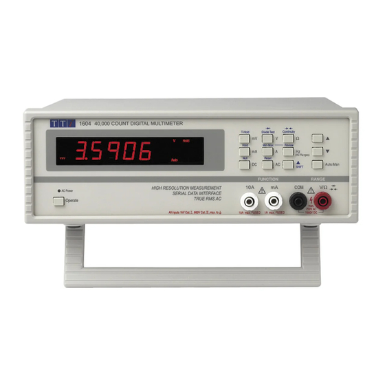
- Page 1 1604 Digital Multimeter Service Manual Book Part Number 48581-1290 - Issue 1...
-
Page 2: Table Of Contents
Table of Contents Specifications Safety Installation General Circuit Descriptions Calibration Fuses Parts List Component Layouts Circuit Diagram... -
Page 3: Specifications
Specifications ACCURACY Accuracies apply for 1 year 19°C to 25°C. Temperature coefficient outside these limits is <0·1 x quoted range accuracy per °C. DC Volts Range Accuracy Resolution Notes 400mV 0·08% ± 4 dig. 10µV 265V DC/AC rms max Input impedance 10MΩ nominal †... - Page 4 DC Current Range Accuracy Resolution Notes 0·1% ± 4 dig. 0·1µA Max. input 1A, 250V, fuse protected 400mA 0·1% ± 4 dig. 10µA Voltage burden <500mV 10A (up to 1A) 0·3% ± 4 dig. 10A (up to 5A) 1·0% ± 4 dig. Max.
- Page 5 DISPLAY Display Type: High brightness LED. Height 0·56” (14mm). Scale Length: 4¾ digits (40,000 counts); AC ranges 4,000 counts. Annunciators: For all ranges, functions and program modes. Reading Rate: 2·5 readings/sec. Overrange: Display shows OFL if input too great for range. GENERAL Power: 115/230 Volts AC nominal 50Hz, adjustable internally;...
-
Page 6: Safety
Safety This multimeter is a Safety Class I instrument according to IEC classification and has been designed to meet the requirements of EN61010-1 (Safety Requirements for Electrical Equipment for Measurement, Control and Laboratory Use). It is an Installation Category II instrument intended for operation from a normal single phase supply. -
Page 7: Emc
The following symbols are used on the instrument: WARNING - risk of electric shock. CAUTION - refer to accompanying documentation; incorrect operation may damage the meter. - mains earth (ground). - direct current - alternating current. This multimeter has been designed to meet the requirements of the EMC Directive 89/336/EEC. Compliance was demonstrated by meeting the test limits of the following standards: Emissions EN50081-1 (1992) Generic emission standard for residential, commercial and light industry. -
Page 8: Installation
Installation Mains Operating Voltage Check that the instrument operating voltage marked on the rear panel is suitable for the local supply. Should it be necessary to change the operating voltage, proceed as follows: 1) Disconnect the instrument from all voltage sources. 2) Remove the main pcb from the case lower as described under ‘Dismantling the Instrument’... -
Page 9: General
General Service Handling Precautions Service work or calibration should only be carried out by skilled engineers. Please note the following points before commencing work. Most of the integrated circuits are CMOS devices and care should be taken when handling to avoid damage by static discharge. -
Page 10: Circuit Descriptions
Circuit Descriptions WARNING: Carefully read the warnings in the Safety section before working on either the main or display/keyboard PCBs. Power Supplies The mains transformer, bridge rectifier and reservoir capacitors provide approximately +10V and - 12V when the instrument is operating. IC17 regulator provides +5V for the microcontroller IC10 and the display. - Page 11 Frequency Measurement Q8 buffers the signal at the Trms AC/DC converter input and drives comparator IC18A. The microcontroller then measures the frequency. IC21A selects between EOC (end of conversion) from the A to D or IC18A for frequency measurement. The output of IC18A is ± 5V; R58 and IC10’s input protection diodes limit the voltage below 0V. Processor, Keyboard and Display The microcontroller, IC10, controls the DMM IC, IC2, together with the display, keyboard and the serial interface.
-
Page 12: Calibration
Calibration Only the case upper needs to be removed for calibration; the screens should be kept in place. Range Apply Adjust mVDC +300mV VR9 for 300.00 ± 2 digits VR3 for 10.000 ± 2 digits 10kΩ 10kΩ 30VDC +30V VR1 for 30.000 ± 2 digits 3VDC VR2 for 3.0000 ±... -
Page 13: Fuses
Fuses The mA socket is protected by a 1A (F) HBC fuse and the 10A socket by a 10A (F) HBC fuse, both mounted internally. To replace a fuse, proceed as follows: 1. Disconnect the instrument from all voltage sources. 2. -
Page 14: Parts List
Parts List PCB ASSY MAIN (44812-0640) Part No. Description Position 10300-0324 PAD P/E S/AD 6 X 3MM FOR XTL1 20030-0263 WASHER M3 ZPST STUDS 20038-9501 WASHER M3 SPRING STUDS 20205-0610 STUD M3 X 10 FOR PJ7 20210-0101 NUT M3 ZPST STUDS 22115-0370 TRANSFORMER... - Page 15 PCB ASSY MAIN (Continued) Part No. Description Position 23202-5100 RES 1M00F W25 MF 50PPM R21, 44, 63 23202-5120 RES 1M20F W25 MF 50PPM 23206-0010 RES 1R00F W60 MF 100PPM R27, 28, 30, 31 23215-0499 RES 49R9B W25 MF 15PPM 23215-2102 RES 1K02B W25 MF 15PPM 23215-2511 RES 5K11B W25 MF 15PPM...
- Page 16 PCB ASSY MAIN (Continued) Part No. Description Position 23620-0242 CAP 22NJ 100V P/E P5 C15,16 23620-0246 CAP 100NK 63V P/E P5 C13,17,19, 32-38, 46, 47, 50, 51 23620-0252 CAP 2N2K 63V P/E P5 23620-0265 CAP 68NK 63V P/E P5 23685-0447 CAP 470PF 630V P/P 23685-0100 CAP 6N80F 63V P/P...
- Page 17 PCB ASSY KEYBOARD (44812-0650) Part No. Description Position 20661-0852 SPACER .56 INCH 7-SEG LED 6.5H FOR DISP1, 2 22226-0140 KEYSWITCH DARK GREY K1-13 22312-0242 FUSE CLIPS PCB MTG FOR FS1, 2 22315-0242 FUSE 10A F HBC 20 x 5MM 22315-9401 FUSE 1A FAST BLOW HBC 23185-0000 RES ZERO OHM...
- Page 18 HANDLE BENCH INST CASE 31346-0200 SCREEN - PCB 33331-4900 FRONT PANEL 33331-4910 OVERLAY FRONT PANEL 33331-4920 REAR PANEL 33536-0820 CASE LOWER 33536-0810 CASE UPPER 37558-1150 LABEL – INSTRUCTION - 1604 48581-1280 INSTRUCTION BOOK 58231-0050 TEST LEAD SET DMM SAFETY 5MM TIP...
-
Page 19: Component Layouts
Component Layouts... -
Page 20: Circuit Diagram
Circuit Diagram... - Page 22 Thurlby Thandar Instruments Ltd Glebe Road, Huntingdon, Cambridgeshire PE29 7DR, England Telephone: (44) 01480 412451 Fax: (44) 01480 450409 e mail: sales@tti-test.com web site: www.tti-test.com...
Need help?
Do you have a question about the 1604 and is the answer not in the manual?
Questions and answers