
Related Manuals for TTI PROFESSIONALS TTICM1000V


Summary of Contents for TTI PROFESSIONALS TTICM1000V
- Page 1 600A AC CLAMP METER AUTO RANGING PART NO: TTICM1000V (..151477) OPERATING INSTRUCTIONS...
-
Page 2: Table Of Contents
CONTENTS INTRODUCTION ......................1 • Intended Use ........................3 • Product Contents ......................3 GENERAL SAFETY ......................3 SAFETY INSTRUCTIONS ....................3 • Safe Operation And Standards ..................4 • Electrical Symbols ......................5 GENERAL SPECIFICATIONS ..................6 EXTERNAL OVERVIEW ....................6 • Function Dial Overview ....................7 • Buttons Overview ......................7 •... -
Page 3: Introduction
INTRODUCTION TTTICM1000V is a true RMS (6000 count) auto ranging digital clamp meter with simulation bar. This meter measures AC Current, AC/DC Voltage, Resistance, Capacitance, Diode Test, Continuity and Non Contact Voltage detection. The instruction manual includes relevant safety information and warning indication, please read them carefully and strictly observes all warnings and notes. -
Page 4: General Safety
GENERAL SAFETY Prior to using the clamp meter, please read the product manual and ensure you have a solid understanding of the devices functions and features. The warnings, cautions, and instructions discussed in this instruction manual cannot cover all possible conditions or situations that could WARNING occur. -
Page 5: Electrical Symbols
soon as the low battery indicator appears. Remove all probes, test leads, and accessories before replacing batteries. • Hold the meter behind the clamp body as specified in “external overview”. • Connect the common test lead before the live test lead and remove the live test lead before the common test lead. -
Page 6: General Specifications
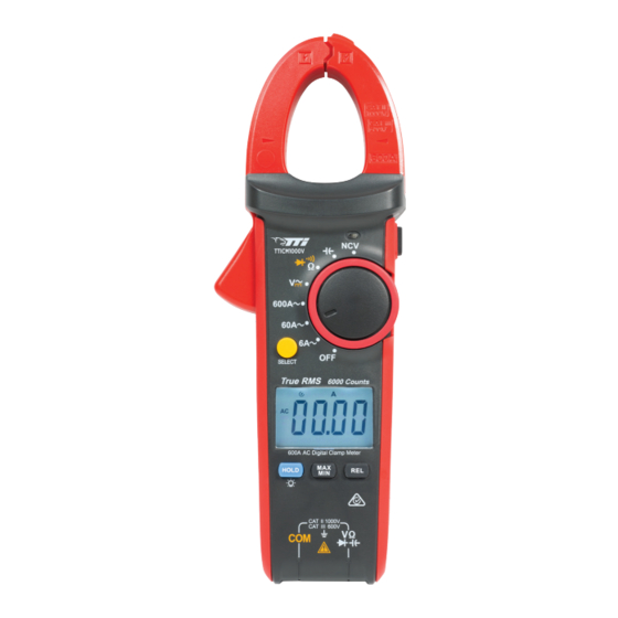
GENERAL SPECIFICATIONS • Display count: approx. 6000 • Sampling rate: 3/s approx. • Sensor type: coil induction • Maximum jaw opening: 30mm • Power supply: 3xAAA 1.5V batteries • Dimension: 228mm x77mm x41mm EXTERNAL OVERVIEW Clamp Clamp body: Designed to protect operator from touching the dangerous area. -
Page 7: Function Dial Overview
FUNCTION DIAL OVERVIEW POSITION DESCRIPTION DC voltage measurement AC voltage measurement AC current measurement DC current measurement Non-contact voltage measurement Diode measurement Continuity measurement Ω Resistance measurement Capacitance measurement Shut-down BUTTONS OVERVIEW BUTTON DESCRIPTION Pressing select allows you to cycle through the options of each function of the multimeter. -
Page 8: Lcd Screen Overview
LCD SCREEN OVERVIEW SYMBOL DESCRIPTION Caution AC/DC voltage is higher than 30V Data hold Negative reading AC/DC AC/DC measurement Low battery indicator Diode measurement Continuity measurement Relative value measurement Ω, k Ω, M Ω Resistance unit mV, V Voltage unit μA, mA, A Current unit nF, μF, mF... -
Page 9: Operating Instructions
OPERATING INSTRUCTIONS AC CURRENT MEASUREMENT Set function selector to , open the meter jaw and clamp the conductor to be measured. Be sure the conductor to be measured is clamped at the centre of the clamp. Care should be taken to ensure that the clamp is completely closed. The current measurement will be shown in the display. -
Page 10: Ac Voltage Measurement
AC VOLTAGE MEASUREMENT Connect common test lead to the COM terminal, then insert the red test lead to V Ω terminal. Set the function selector to the V setting and connect the test lead in parallel with the power or load to be measured. The meter will auto-range to display the most appropriate measurement. -
Page 11: Dc Voltage Measurement
DC VOLTAGE MEASUREMENT Connect common test lead to the COM terminal, then insert the red test lead to V Ω terminal. Set the function selector to and connect the test lead in parallel with the power or load to be measured. The meter will auto-range to display the most appropriate measurement. -
Page 12: Resistance Measurement
RESISTANCE MEASUREMENT • To avoid damaging the meter or to the device under test, disconnect circuit power and discharge all the high-voltage capacitors before WARNING measuring resistance. • To avoid electric shock, do not input higher than DC 60V or AC 30V voltages. -
Page 13: Continuity Testing
CONTINUITY TESTING • To avoid damaging the meter or to the device when testing, disconnect circuit power and discharge all the high-voltage capacitors before WARNING testing for continuity. • To avoid electric shock, do not input higher than DC 60V or AC 30V Connect common test lead to the COM terminal, then insert the red test lead to V Ω... -
Page 14: Diode Testing
DIODE TESTING • To avoid possible damage to the meter and to the device under test, disconnect circuit power and discharge all high-voltage capacitors WARNING before testing diodes. • To avoid electric shock, do not input higher than DC 60V or AC 30V Connect common test lead to the COM terminal, then insert the red test lead to V Ω... -
Page 15: Capacitance Measurement
CAPACITANCE MEASUREMENT To avoid possible damage to the meter and to the device under test, disconnect circuit power and discharge all high-voltage capacitors before WARNING measuring capacitance. Use the DC Voltage function to confirm that the capacitor is discharged. Connect common test lead to the COM terminal, then insert the red test lead to V Ω terminal. -
Page 16: Non-Contact Ac Voltage Detecting (Ncv)
NON-CONTACT AC VOLTAGE DETECTING (NCV) In order to sense whether there is AC voltage or electromagnetic field in this space, place the front end of the clamp meter near the conductor to be tested (distance <10mm). When an electric field voltage is detected (100vRMS), the meter will beep with a red light above the NCV dial. -
Page 17: Technical Index
TECHNICAL INDEX ENVIRONMENTAL CONSTRAINT WORKING HEIGHT Indoor altitude 2000m POLLUTION GRADE 0°C~30 °C (not bigger than 80%RH) OPERATING HUMIDITY & TEMPERATURE 30°C~40°C (not bigger than 75%RH) 40°C~50°C (not bigger than 45%RH) STORAGE HUMIDITY & TEMPERATURE -20°C~60°C (not bigger than 80%RH) ELECTRICAL SPECIFICATION AC RANGE RESOLUTION... -
Page 18: Resistance Measurement
RESISTANCE MEASUREMENT RANGE RESOLUTION ACCURACY OVERLOAD PROTECTION 600Ω 0.1Ω ±(1.2%+2) 6kΩ 0.001kΩ 60kΩ 0.01kΩ ±(1.0%+2) 1000V DC 750 V AC 600kΩ 0.1kΩ 6MΩ 0.001MΩ ±(1.2%+2) 60MΩ 0.01MΩ ±(1.5%+5) CAPACITANCE MEASUREMENT RANGE RESOLUTION ACCURACY OVERLOAD PROTECTION 99.99nF 0.01nF ±(4.0%+25) 999.99nF 0.1nF 9.999nF 0.001nF ±(4.0%+5) -
Page 19: Diode Measurement
DIODE MEASUREMENT OVERLOAD RANGE RESOLUTION PROTECTION 1000V DC 0.001V 750V AC POWERING OFF To power off the clamp meter, move the function selector to the off position. Power off the device after each use to conserve battery. The clamp meter will auto power off if not used for 15min. To wake up the clamp meter, press any button or move the function dial. -
Page 20: Warranty Information
WARRANTY INFORMATION This warranty is provided by Total Tools (Importing) Pty Ltd of 20 Thackray Road, Port Melbourne VIC 3207. Phone: 03 9261 1900 (we, us, our). Express Warranty Subject to the exclusions set out below, we warrant that this product will be free from defects in materials or workmanship for 12 months from the date of purchase.
Need help?
Do you have a question about the PROFESSIONALS TTICM1000V and is the answer not in the manual?
Questions and answers