Table of Contents
Advertisement
Quick Links
Advertisement
Table of Contents

Related Manuals for TTI TTIDM1000VAR


Summary of Contents for TTI TTIDM1000VAR
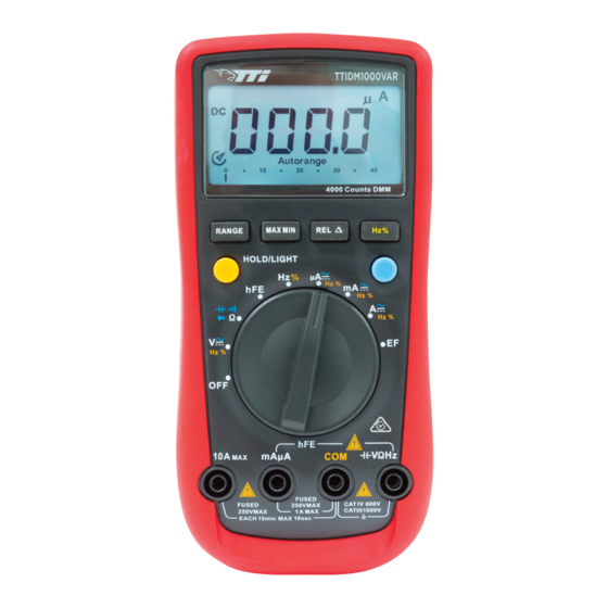
- Page 1 AUTO-RANGING MULTIMETER PART NO: TTIDM1000VAR (..151475) OPERATING INSTRUCTIONS...
-
Page 2: Table Of Contents
CONTENTS INTRODUCTION ......................3 • Intended Use ............................3 • Product Contents ..........................3 • Electrical Symbols ..........................3 GENERAL SAFETY ......................4 SAFETY INSTRUCTIONS ....................4 • Safety Standards ..........................4 • Guide For Safe Operation ........................4 GENERAL SPECIFICATIONS ..................6 EXTERNAL OVERVIEW ....................7 • Function Dial Overview ........................7 •... -
Page 3: Introduction
INTRODUCTION TTIDM1000VAR is a professional auto ranging multimeter. The multimeter comes with the following features: AC/DC current measurement up to 10A AC voltage measurement up to 750V DC voltage measurement up to 1000V hFE & EF function Diode test Data hold... -
Page 4: General Safety
GENERAL SAFETY Prior to using the meter, read the product manual and ensure you have a solid understanding of the machines functions and features. The warnings, cautions, and instructions discussed in this instruction manual cannot cover all possible conditions or situations that could WARNING occur. - Page 5 • Use Product-approved measurement category (CAT), voltage, and amperage rated accessories (probes, test leads, and adapters) for all measurements. • Use the correct terminals, function, and range for measurements. • Before each use, verify meter operation by measuring a known voltage first. •...
-
Page 6: General Specifications
GENERAL SPECIFICATIONS Maximum Voltage between any terminals and grounding: please refer to the technical index for more details. Fused Protection for µAMA Input Terminal:1A H 240V Φ6x25mm. Fused Protection for 10A Input Terminal:10A H 240V Φ6x25mm. Display: Maximum reading 4000 (frequency 9999), analogue bar graph 41 segments Measurement Speed: Updates 2~3 times/second. -
Page 7: Function Dial Overview
FUNCTIONAL DIAL OVERVIEW POSITION DESCRIPTION AC and DC voltage measurement Ω Resistance measurement µ Diode test Continuity test Capacitance test Frequency and duty cycle test Transistor measurement μ A DCA and ACA measurement DCmA and ACmA measurement 10A DC and AC measurement Sensor test Shut-down LCD SCREEN OVERVIEW... -
Page 8: Buttons Overview
Data output is in progress Warning: To avoid false readings, which could lead to possible electric shock or personal injury, replace the battery as soon as the battery indicator appears. Sensor test is in progress The REL is on to display the stored value minus the present value •... - Page 9 • Press to enter REL mode. • Press again to exit REL mode μ MAXMIN MkΩ β Autorange 4000 Counts DMM RANGE MAX/MIN HOLD/LIGHT µ Ω VΩHz mA µA FUSED FUSED 250V MAX CAT IV 600V 250V MAX 1A MAX CAT III 1000V EACH 15min MAX 10sec CAT II 1000V...
-
Page 10: Operating Instructions
OPERATING INSTRUCTIONS AC/DC VOLTAGE MEASUREMENT To avoid electric shock or damage to the meter, do not attempt to WARNING measure voltages higher than the rated voltage (AC 750V, DC 1000V). When measuring high voltages, take extra care to avoid electric shock. When connecting the test leads to the circuit or device, connect the common (COM) test lead before connecting the live lead;... -
Page 11: Ac/Dc Current Measurement
AC/DC CURRENT MEASUREMENT • Never attempt to make an in-circuit current measurement when the open-circuit potential to earth is >600 V. • To prevent possible electric shock, fire or personal injury, switch off the power supply of the circuit before measuring the current, and then connect the meter with the circuit in series. -
Page 12: Resistance Measurement
RESISTANCE MEASUREMENT • To avoid damaging the meter or to the device under test, disconnect circuit power and discharge all the high-voltage capacitors before WARNING measuring resistance. • To avoid electric shock, do not input higher than DC 60V or AC 30V voltages. -
Page 13: Continuity Measurement
CONTINUITY MEASUREMENT • To avoid damaging the meter or to the device when testing, disconnect circuit power and discharge all the high-voltage capacitors before WARNING testing for continuity. • To avoid electric shock, do not input higher than DC 60V or AC 30V Use the continuity function as a fast, convenient method to check for opens and shorts. -
Page 14: Diode Measurement
DIODE MEASUREMENT • To avoid possible damage to the meter and to the device under test, disconnect circuit power and discharge all high-voltage capacitors WARNING before testing diodes. • To avoid electric shock, do not input higher than DC 60V or AC 30V Connect the common test lead to COM terminal then insert the red test lead into the ΩHz. -
Page 15: Capacitance Measurement
CAPACITANCE MEASUREMENT To avoid possible damage to the meter and to the device under test, disconnect circuit power and discharge all high-voltage capacitors before WARNING measuring capacitance. Use the DC Voltage function to confirm that the capacitor is discharged. To measure capacitance, connect the meter as per below: Connect the common test lead to COM terminal then insert the red test lead into the ΩHz. -
Page 16: Frequency Measurement
FREQUENCY MEASUREMENT To avoid personal harm, do not attempt to input higher than 30V rms WARNING tested frequency voltage To measure frequency, connect the meter as per below: Connect the common test lead to COM terminal then insert the red test lead into ΩHz. -
Page 17: Ef Function
EF FUNCTION To use EF function, connect the meter as followed: Set the function selector to EF and place the front of the multimeter towards the object being measured. *Test leads not required. When the meter detects an Electric Field the LCD displays digits representing the strength of the field. -
Page 18: Range Button
RANGE BUTTON • Press RANGE to enter the manual ranging mode. • Press RANGE to step through the ranges available for the selected function. • Press and hold RANGE for over 2 seconds to return to auto-ranging. MAX/MIN BUTTON • Press MAX MIN to start recording of maximum and minimum values. -
Page 19: Technical Index
TECHNICAL INDEX ACCURACY SPECIFICATIONS • Accuracy ± a% reading + b digits (guaranteed for 1 year). • Operating temperature 18°C~28°C. • Relative humidity <75%. DC VOLTAGE MEASUREMENT RANGE RESOLUTION ACCURACY INPUT IMPEDANCE FIXED VALUE INPUT 40mV 0.01mV ± (0.8%+3) Around >3000MΩ 400mV 0.1mV ±... -
Page 20: Dc Current Measurement
DC CURRENT MEASUREMENT RANGE RESOLUTION ACCURACY OVERLOAD PROTECTION 400µA 0.1µA (1.0%+2) 4000µA 1µA Fuse 1: F1A H 240V (CE), <D6 x25mm 40mA 0.01mA (1.2%+3) 400mA 0.1mA 0.001A Fuse 2: F10A H 240V (1.5%+3) (CE),<D6 x 25mm 0.01A AC CURRENT MEASUREMENT RANGE RESOLUTION ACCURACY... -
Page 21: Capacitance Measurement
CAPACITANCE MEASUREMENT RANGE RESOLUTION ACCURACY OVERLOAD PROTECTION REMARKS 40nF 0.01nF 400nF 0.1nF ±(3.0%+5) There is around 4µF 0.001µF 1000V DC 10nF residual /750 AC reading when the 40µF 0.01µF circuit is open 400µF 0.1µF ±(4.0%+5) 4000µF 1µF Unspecified FREQUENCY MEASUREMENT RANGE ACCURACY MAX RESOLUTION... -
Page 22: Maintenance
MAINTENANCE Do not attempt to repair or service the meter unless you are qualified WARNING to do so and have the appropriate calibration, performance test and service tools. If not, consult you Total Tools store for repair/service. To avoid electrical shock or damage to the meter, do not get expose the meter to water or have it submerged in water. -
Page 23: Fuse Replacement
FUSE REPLACEMENT To avoid electrical shock or arc blast, or personal injury or damage to WARNING the Meter, use specified fuses ONLY in accordance with the following procedure. To test the fuse: If the meter does not respond when measuring current and transistor hFE, inspect the meter’s built-in fuses to see if they are blown. -
Page 24: Warranty Information
WARRANTY INFORMATION This warranty is provided by Total Tools (Importing) Pty Ltd of 20 Thackray Road, Port Melbourne VIC 3207. Phone: 03 9261 1900 (we, us, our). Express Warranty Subject to the exclusions set out below, we warrant that this product will be free from defects in materials or workmanship for 12 months from the date of purchase.
Need help?
Do you have a question about the TTIDM1000VAR and is the answer not in the manual?
Questions and answers