Advertisement
Quick Start
Quick Start
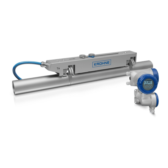
OPTISONIC 6300 F/...Ex
Ultrasonic clamp-on flowmeter
Installation, assembly, start-up and maintenance may only be performed by appropriately trained personnel.
Check the nameplate for correct operating conditions.
For use in hazardous areas, special codes and regulations are applicable. Instruments must not be
connected to power supply before reading instructions described in the supplementary manual.
The responsibility as to the suitability, intended use and corrosion resistance of the used materials against
the measured fluid of this device rests solely with the operator.
For complete documentation (manuals, supplementary manuals, data sheets and certificates) please refer
to:
www.krohne.com/Downloads
Special conditions to be observed
● For ambient and process temperatures, specific product and electrical data, see Ex manual or certificate
● For dimensions and details of the flameproof joints, the manufacturer shall be contacted
● The tensile strength of the special fasteners is at least 700 N/mm² (property class A2-70 / A4-70)
● The protection class of the signal converter enclosure is according EN 60529: IP65...68
● All connection cables are fixed and installed correctly so adequate protection against possible damage is
guaranteed
● Only for connection to a separately certified UFC 300 F/...Ex flow converter
● The instructions provided with the product shall be followed in detail to assure safe operation
Ex ► Type Examination Certificate: KIWA 17ATEX 0034 X / KIWA 18ATEX0007 X
General
Ta = -40...+70°C / -40...+158°F
Tp = -40...+200°C / -40...+392°F
Maximum ambient and process temperatures
are depending on version (e.g liner material , DN
size), temperature and protection class and
maximum surface temperature of sensor.
12/2020 - 4008317001 - OPTISONIC 6300 F/...Ex R01 en
Diameter range and rail versions
Small
DN15...100 / 0.5...4"
DN200...1250 / 8...50"
Small
Medium
DN50...400 / 2...16"
DN200...4000 / 8...160"
Preferred measuring modes
General
System Configuration
1 Electrical connection
All work on the electrical connections may only be carried out with the power disconnected. Take note of the
voltage data on the nameplate! Observe the national regulations for electrical installations!
Observe without fail the local occupational health and safety regulations. Any work done on the electrical
components of the measuring device may only be carried out by properly trained specialists.
Electrical connections signal converter
2 3
1
Medium
Large
1
1
For initial set up, we strongly recommend the use of the relevant manuals in addition!
Device nameplate
Check the device nameplate to ensure that the device is
delivered according to your order.
3
2
100...230VAC (-15% / +10%), 22VA
24VDC (-55% / +30%), 12W
24VAC/DC (AC: -15% / +10%; DC: -25% / +30%),
22VA or 12W
The device must be grounded in accordance with
regulations in order to protect personnel against electric
shocks.
For devices used in hazardous areas, additional safety
notes apply; please refer to the Ex documentation.
Refer to the manual for connection of Ex (/i ) acc. to
NAMUR
1
Sensor cable connections
2
3
2
I/O connections
3
Mains supply connection
Power supply - grounding
2
Advertisement
Table of Contents

Related Manuals for KROHNE OPTISONIC 6300 F Ex Series


Summary of Contents for KROHNE OPTISONIC 6300 F Ex Series
- Page 1 For complete documentation (manuals, supplementary manuals, data sheets and certificates) please refer System Configuration www.krohne.com/Downloads 1 Electrical connection All work on the electrical connections may only be carried out with the power disconnected. Take note of the...
- Page 2 2 Installation General installation of the rails Greasing the transducer surfaces ≥ 10 × ∅ ≥ 5 × ∅ ≥ 20 × ∅ 120 ° Installation position Pump, control valve - open feed / discharge Check the OPTISONIC 6300 manual for more details on installation options (e.g.
- Page 3 3 Installation menu X 4 Quick Setup Measuring mode Select menu Select Submenu Functions Status message ↑ ↓ ↑ ↓ ↑ ↓ > Press > 2.5 s Tag number X1 language X Installation Measured variable X2 GDC IR interface ↵ >...
- Page 4 Contact Current output passive Ip (modular/Ex i I/O) Control input passive Cp, (modular/Ex i I/O) To view all KROHNE locations and contact details visit: www.krohne.com Then “Select your country“ from the drop-down list at the top Control input active CN to NAMUR, (modular I/O)
Need help?
Do you have a question about the OPTISONIC 6300 F Ex Series and is the answer not in the manual?
Questions and answers