Table of Contents

Related Manuals for AERMEC IDROSPLIT


Summary of Contents for AERMEC IDROSPLIT
- Page 1 Sistema autonomo di condizionamento e riscaldamento Independent air conditioning and heating system IDROSPLIT COMP ANY QUALITY SYSTEM ISO 9001 - Cert. n° 0128/1 CISQ IIDUW Sostituisce il: 9801 Replace: 63774.06 63774.04 / 9601 AERMEC S.P.A.
- Page 3 INFORMAZIONI GENERALI • GENERAL INFORMATION CARATTERISTICHE • FEATURES Descrizione dell’unità • Unit Description Scopo della macchina • Purpose of the machine Componenti principali • Main components Versioni disponibili • Versions available Descrizione dei componenti • Description of components Organi di sicurezza e regolazione • Safety and control devices Intervento delle sicurezze •...
- Page 5 Telefax (0442) 93577 – 93566 Il presente prodotto deve essere installato, esclusivamente, The above equipment must be used with AERMEC unit CX in abbinamento con le unità CX o CWX di nostra produzio- or CWX series only. This combinations are clearly shown in ne.
- Page 6 DESCRIZIONE DELL’UNITÀ • UNIT DESCRIPTION SCOPO DELLA MACCHINA PURPOSE OF THE MACHINE Idrosplit è un apparecchio adatto alla realizzazione di impian- The Idrosplit is suitable for constructing packaged plants for the summer air-conditioning of small to medium sized loca- ti autonomi per il condizionamento estivo di piccole-medie utenze in edifici di carattere residenziale e commerciale.
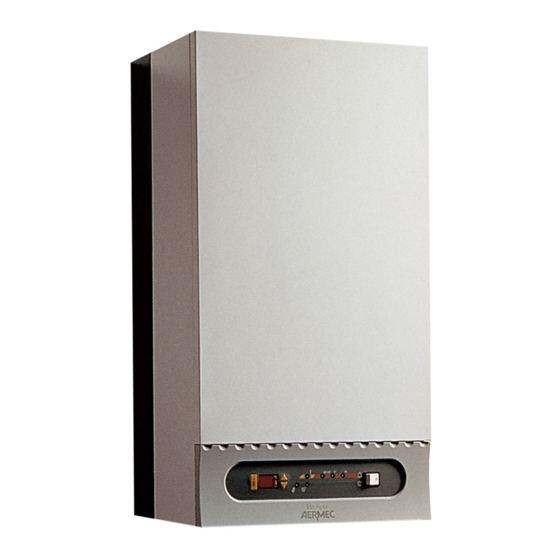
- Page 7 ID 51 ID 51 DESCRIZIONE DEI COMPONENTI • COMPONENT DESCRIPTION MODULO IDROSPLIT ( ID ) IDROSPLIT MODULE (ID) Il modulo ID deve essere installato all’interno. The ID module must be installed indoors. Il mobile di copertura, elegante e adatto ad essere installato The outer cabinet, elegant and suitable for installation even in vista, è...
- Page 8 - il pressostato di alta pressione, a norme TÜV, di tipo - the low pressure switch, to protect the evaporator on the miniguard a taratura fissa; Idrosplit in case of abnormal operating conditions. - il pressostato di bassa pressione, per la protezione - the high pressure service point.
- Page 9 TERMOSTATO ANTIGELO ANTIFREEZE THERMOSTAT Protegge lo scambiatore e i componenti interni dell’Idrosplit It protects the Idrosplit’s exchanger and internal compo- dal pericolo di gelo. nents against the risk of freezing.
- Page 10 IMBALLO • PACKING Le unità vengono spedite con imballo standard costituito da The units are shipped with the standard packing, including una scatola di cartone con protezioni in polistirolo espanso. a cardboard carton with polystyrene foam padding. Per particolari esigenze, su richiesta, l’imballo standard può On request, for specific requirements, the standard packing essere completato con una gabbia di legno.
- Page 11 – tensione di alimentazione: 220 V (380 V per mod. T). – power supply: 220 V (380 V for mod. T). N.B. = Il circolatore del modulo Idrosplit è commutato alla N.B. = The Idrosplit module water pump is at medium media velocità...
- Page 12 SCHEMA DI FUNZIONAMENTO • OPERATING SCHEME 1 pressostato differenziale IDROSPLIT differential pressure switch 2 vaso di espansione expansion tank 3 pompa water pump 4 serbatoio di accumulo water tank 5 evaporatore a piastre plate heat exchanger 6 attacchi a cartella...
- Page 13 L’ALIMENTAZIONE CON ACQUA CALDA • SUPPLY OF HOT WATER Il modulo Idrosplit può essere alimentato con una portata di The Idrosplit module can use hot water from any form of acqua calda di qualsiasi provenienza; in ogni caso, per supply. In any case to guarantee a proper operation of the garantire un buon funzionamento del sistema è...
- Page 14 Idrosplit reduces the commitment of absorbed electric Nel condizionamento estivo, la potenza ridotta di Idrosplit power and falls into the category of contracts usually stipu- consente di limitare l’impegno di potenza elettrica assorbita lated with the Electricity Board for the supply of civil resi- e di rientrare nei contratti normalmente stipulati con l’ENEL...
- Page 15 è, con molta lable head available on the hot water circuit downstream to the Idrosplit (both if the source is a boiler pump or centrali- probabilità, il caso più sfavorevole, perchè la prevalenza che si ha a disposizione sul circuito caldo a valle sed pump, etc.
- Page 16 - nello stesso diagramma, si tracci la caratteristica resistente del circuito alla temperatura di funzionamento estivo (per the Idrosplit pump operates), read off table 5 or 6 (curve 4). esempio 10 °C); questa si ottiene moltiplicando il valore Then the operating point of the plant can be traced (flow - head) as the point where the two curves intersect.
- Page 17 ) in an apartment block. L’impianto dovrà realizzare il riscaldamento invernale ed il The plant must provide winter heating and summer air-con- ditioning. The Idrosplit module is used in conjunction with condizionamento estivo; si utilizza il modulo Idrosplit asso- ciato ad una caldaia murale.
- Page 18 1,2 m /h, la prevalenza the Idrosplit module. From the available head, we must then utile sia pari a 2,3 m C.A. Tale portata, prima di raggiungere subtract the pressure drops of the Idrosplit module. The il circuito utilizzatore, passa attraverso il modulo Idrosplit: chart in table 7 gives, in correspondence to 1.200 l/h, a...
- Page 19 ciente k=1,7÷(1,2) =1,18 (curva 1). Now, with the same hydraulic circuit, the pressure drops Ora, a parità di circuito idraulico, le perdite di carico increase with the decreasing of the average water flow tem- aumentano al diminuire della temperatura media della por- perature.
- Page 20 TAV 1 POTENZA FRIGORIFERA TOTALE ED ASSORBIMENTO ELETTRICO TOTALE COOLING CAPACITY AND TOTAL INPUT POWER Mod. ID 31 + CWX 166 1,58 1,56 1,54 1,52 frig/h x 1.000 °C Temperatura uscita acqua • Water outlet temperature = temperatura di condensazione condensing temperature...
- Page 21 TAV 2 POTENZA FRIGORIFERA TOTALE ED ASSORBIMENTO ELETTRICO TOTALE COOLING CAPACITY AND TOTAL INPUT POWER Mod. ID 31 + CX 166 frig/h x 1.000 °C Temperatura uscita acqua • Water outlet temperature = temperatura aria esterna outdoor air temperature...
- Page 22 TAV 3 POTENZA FRIGORIFERA TOTALE ED ASSORBIMENTO ELETTRICO TOTALE COOLING CAPACITY AND TOTAL INPUT POWER Mod. ID 51 + CWX 266 Per il mod. CWX 266 T sottrarre 50 W alla Potenza totale assorbita For CWX 266 T model subtract 50 W from Total Power Input 2,38 2,36 2,34...
- Page 23 TAV 4 POTENZA FRIGORIFERA TOTALE ED ASSORBIMENTO ELETTRICO TOTALE COOLING CAPACITY AND TOTAL INPUT POWER Mod. ID 51 + CX 266 Per il mod. CX 266 T sottrarre 50 W alla Potenza totale assorbita For CX 266 T model subtract 50 W from Total Power Input frig/h x 1.000 °C Temperatura uscita acqua •...
- Page 24 PREVALENZA UTILE NEL FUNZIONAMENTO ESTIVO EFFECTIVE PRESSURE DURING SUMMER OPERATION TAV. 5 Mod. ID 31 kPa 90 9 m C.A. Max. vel. - speed Med. vel. - speed (standard) 800 1000 1200 1400 1600 1800 2000 2200 l/h Portata acqua • Water flow TAV.
- Page 25 PERDITE DI CARICO INTERNE NEL FUNZIONAMENTO INVERNALE INTERNAL PRESSURE DROPS DURING WINTER OPERATION TAV. 7 Mod. ID 31 - ID 51 kPa 20 2 m C.A. 800 1000 1200 1400 1600 1800 2000 2200 l/h Portata acqua • Water flow CONSUMO D’ACQUA E PERDITE DI CARICO DEL CONDENSATORE CONDENSER WATER CONSUMPTION AND PRESSURE DROPS TAV.
- Page 26 POTENZA FRIGORIFERA RESA NEL FUNZIONAMENTO ESTIVO COOLING CAPACITY DURING SUMMER OPERATION Mod. FCX 16 TAV. 9 Mod. FCX 21 TAV. 10 kW 2 kW 1,3 TIA1 TIA1 TIA2 TIA2 TIA3 TIA3 400 l/h Portata acqua • Water flow 600 l/h Portata acqua •...
- Page 27 POTENZA TERMICA RESA NEL FUNZIONAMENTO INVERNALE HEATING CAPACITY DURING WINTER OPERATION Mod. FCX 16 TAV. 13 Mod. FCX 21 TAV. 14 kW 5 ∆ t = 50 ° C kW 3,5 ∆ t = 50 ° C ∆ t = 40 ° C ∆...
- Page 28 POTENZA FRIGORIFERA RESA NEL FUNZIONAMENTO ESTIVO COOLING CAPACITY DURING SUMMER OPERATION Mod. FCD 11 TAV. 17 Mod. FCD 16 TAV. 18 kW 1,4 kW 1,45 TIA1 1,35 TIA1 TIA2 TIA2 1,25 TIA3 1,15 1,05 TIA3 0,95 0,85 0,75 400 l/h 300 l/h Portata acqua •...
- Page 29 POTENZA TERMICA RESA NEL FUNZIONAMENTO INVERNALE HEATING CAPACITY DURING WINTER OPERATION Mod. FCD 11 TAV. 21 Mod. FCD 16 TAV. 22 kW 2,5 kW 3,4 ∆t = 50 °C ∆t = 50 °C ∆t = 40 °C ∆t = 40 °C ∆t = 30 °C ∆t = 30 °C 400 l/h...
- Page 30 TAB A PORTATA D’ARIA DEI VENTILCONVETTORI FAN COIL AIR FLOW RATE Mod. FCX 16 FCX 21 FCX 31 FCX 41 max. Velocità med. Speed min. Mod. FCD 11 FCD 16 FCD 26 FCD 36 max. Velocità med. Speed min. TAB B PERDITE DI CARICO DEI VENTILCONVETTORI LATO ACQUA FAN COIL WATER PRESSURE DROP Portata acqua...
- Page 31 TAB D FATTORI DI CORREZIONE DEI VENTILCONVETTORI FAN COIL CORRECTION FACTOR Mod. FCD 11 FCD 16 FCD 26 FCD 36 Velocità media • Medium speed 0,79 0,80 0,85 0,88 Velocità minima • Low speed 0,67 0,62 0,65 0,70 Velocità media resa totale •...
- Page 32 USI IMPROPRI • IMPROPER USES L'apparecchio è progettato e costruito per garantire la massima The unit is designed and constructed to guarantee maximum safety sicurezza nelle sue immediate vicinanze, nonchè per resistere agli in its immediate proximity, and to resist weathering. The outdoor agenti atmosferici.
- Page 33 Sistema Idrosplit the case of installation of the complete Idrosplit system. The condensing unit shown in the figure (CX) uses outdoor air to completo.
- Page 34 COLLEGAMENTI IDRAULICI • WATER CONNECTIONS The Idrosplit module must be connected to the boiler or Il modulo Idrosplit deve essere collegato alla caldaia autono- ma od all’impianto di riscaldamento centralizzato. La distri- central heating plant.
- Page 35 Fig. 4 61 34 ASOLA 15 X 8,5 HOLE ø = 22 ø = 8,5 ø = 28 Attacchi Freon mm 155 Gas Connections Attacchi idraulici mm 165 Water connections Mandata impianto Linee Mandata Caricamento Fig. 5 frigorifere Chilled water caldaia Ritorno impianto Ritorno caldaia...
- Page 36 Il modello trifase è dotato di un apposito relè (RPF), che With reference to the wiring diagram of the Idrosplit modu- verifica la sequenza delle fasi dell’alimentazione elettrica di le, you will find available: rete e del compressore.
- Page 37 Fig. 8 Fig. 9 Fig. 10 Fig. 11 Fig. 12...
- Page 38 4- Raccordi linea carica • Fill connections 5- By pass 6- Spezzone cieco • Blanking piece 1 6 0 KIT "PREDISPOSIZIONE IDROSPLIT" COMPOSTO DA DUE ACCESSORI: DIMA 1 / RACCORDI 3-4-5-6 "IDROSPLIT PREARRANGEMENT": TWO ACCESSORIES Fig. 13 TEMPLATE (1) AND COUPLINGS (3-4-5-6)
- Page 39 INSTRUCTIONS FOR USE L’impianto di riscaldamento-condizionamento realizzato The heating-air-conditioning plant created with the Idrosplit con il sistema Idrosplit è caratterizzato da un’estrema faci- system is distinguished by an extremely easy to use. lità d’uso. The user can in fact, by simply pressing a switch, convert operation from winter to summer and, turning the fancoils L’utente può...
- Page 40 (potrebbero essere tutti quelli installati o solo in circulation, and the rooms served would only be partially cooled. Idrosplit warns the user of this situation by lighting alcuni: dipende dai carichi termici relativi ai vari ambienti). Se si mettessero in funzione più ventilconvettori di quanto up the overload pilot light (see below).
- Page 41 - display (3) che visualizza la temperatura dell’acqua di - display (3) which shows the return water temperature or, ritorno dall’impianto o, in alternativa, quella di set-point; in alternative, the set-point; - tasti (4) per la modifica della temperatura impostata; - keys (4) to adjust the temperature setting;...
- Page 42 DIMENSIONI • DIMENSIONS (mm) Mod. ID 31 ID 51 CWX 166 CX 166 CWX 266 CX 266 (mm) (mm) (mm) Peso • Weight (kg) SPAZI TECNICI MINIMI • MINIMUM TECHNICAL SPACE (mm) INSTALLAZIONE A PAVIMENTO INSTALLAZIONE CON MENSOLA FLOOR INSTALLATION INSTALLATION WITH SUPPORTS Mod.
- Page 43 LEGENDA PER SCHEMI ELETTRICI • WIRING DIAGRAMS KEY = Pressostato di alta pressione = Relè sequenza fasi High pressure switch Phase sequence check relay = Pressostato di bassa pressione = Relè termico Low pressure switch Thermic relay = Contattore compressore = Scheda elettronica Compressor contactor Electronic control board...
- Page 44 SCHEMI ELETTRICI • WIRING DIAGRAMS CWX 166 CX 166 CWX 266 CX 266 Gli schemi elettrici sono soggetti ad aggiornamento; è opportuno fare riferimento allo schema elettrico allegato all'apparecchio. Wiring diagrams may change for updating. It is therefore necessary to refer always to the wiring diagram inside the units.
- Page 45 SCHEMI ELETTRICI • WIRING DIAGRAMS CWX 266 T CX 266 T Gli schemi elettrici sono soggetti ad aggiornamento; è opportuno fare riferimento allo schema elettrico allegato all'apparecchio. Wiring diagrams may change for updating. It is therefore necessary to refer always to the wiring diagram inside the units.
- Page 48 Technical data shown in this booklet are not binding. gnativi. Aermec S.p.A. shall have the right to introduce at any time whatever L’Aermec S.p.A. si riserva la facoltà di apportare in qualsiasi momen- modifications deemed necessary to the improvement of the product.
Need help?
Do you have a question about the IDROSPLIT and is the answer not in the manual?
Questions and answers
Ho un impianto per il raffreddamento aria Aermec idosplit non funziona più non trovo chi lo sostituisce o lo ripara.
Contact the local Aftersales Service immediately for replacement or repair of the AERMEC IDROSPLIT air cooling system.
This answer is automatically generated