AERMEC FCL 32 Installation Manual
Cassette-type fan coil
Hide thumbs
Also See for FCL 32:
- Installation manual (89 pages) ,
- Technical manual (85 pages) ,
- Installation manual (86 pages)
Advertisement
VENTILCONVETTORE CASSETTE
CASSETTE-TYPE FAN COIL
VENTILO-CONVECTEUR À CASSETTE
KASSETTEN-GEBLÄSEKONVEKTOR
FAN COIL TIPO CASSETTE
FCL
FCL 32
(600x600)
FCL 36
(600x600)
FCL 42
(600x600)
FCL 62
(600x600)
FCL 72
(600x600)
FCL 34
(600x600)
FCL 38
(600x600)
FCL 44
(600x600)
FCL 64
(600x600)
Sostituisce il • Replace • Remplace le n° • Ersetzt • Sustituye a: 4528500_03 / 1012
MANUALE INSTALLAZIONE
I N S T A L L A T I O N
M A N U E L D ' I N S TA L L AT I O N
INSTALLATIONSHANDBUCH
M A N U A L
I N S T A L A C I Ó N
FCL 82
(840x840)
FCL 102
(840x840)
FCL 122
(840x840)
FCL 84
(840x840)
FCL 104
(840x840)
FCL 124
(840x840)
IFCLIJ 1107 - 4528500_04
M A N U A L
Advertisement
Table of Contents

Related Manuals for AERMEC FCL 32


Summary of Contents for AERMEC FCL 32
- Page 1 M A N U A L I N S T A L A C I Ó N VENTILCONVETTORE CASSETTE CASSETTE-TYPE FAN COIL VENTILO-CONVECTEUR À CASSETTE KASSETTEN-GEBLÄSEKONVEKTOR FAN COIL TIPO CASSETTE FCL 32 FCL 82 (600x600) (840x840) FCL 36 FCL 102 (600x600)
- Page 2 Insbesondere auf die sich für die Garantiearbeiten als erforderlich erweisen sollten. Benutzungsanweisungen mit den Hinweisen "VORSICHT" Die AERMEC S.p.A. übernimmt keine Haftung für Schäden aus oder "ACHTUNG" achten, da deren Nichtbeachtung Schäden dem unsachgemäßen Gebrauch des Gerätes und der teilweisen am Gerät bzw.
- Page 3 FCL + ZUBEHÖR sont pas fournis de Aermec. Falls das Gerät mit Zubehörteilen ausgerüstet wird, die nicht von Aermec geliefert werden, ist dessen Inbetriebnahme solange untersagt DECLARACIÓN DE CONFORMIDAD Los que suscriben la presente declaran bajo la propia y exclusiva responsabilidad que el conjunto en objeto, defi...
- Page 4 TRASPORTO • CARRIAGE • TRANSPORT • TRANSPORT • TRANSPORTE NON bagnare. Tenere al riparo NON calpestare dalla pioggia Do NOT step Do NOT wet NE PAS marcher sur cet emballage CRAINT l’humidité Nicht betreten Vor Nässe schützen NO pisar NO mojar Sovrapponibilità: controllare sull’imballo per conoscere il numero di macchine FCL (840x840) FCL (600x600)
- Page 5 INDEX Important information • Maintenance • Packaging Functions Description • Versions • Functioning limits Main components • Component description Installation of the unit Connections Installation and replacement of the filter Dimensions Wiring diagrams IMPORTANT INFORMATION AND MAINTENANCE ATTENTION: the fan coil is connected sensation and consequently discomfort.
- Page 6 FUNCTIONING The same FCL unit can be coupled to - GLL10 / GLL20 - GLL10M / GLL10R / GLL20R several grid accessories that determine If an electronic control panel is to be Check that the Dip Switch settings inside different functioning modes. installed, check that the Dip Switch the electric box correspond to system The particular information is supplied...
- Page 7 USE (MODULE 600) In heating functioning mode, In cooling functioning mode, Ventilation is allowed with the a louvered fin opening of 20° is a louvered fin opening of 10° is louvered fins closed. recommended, indicated with a recommended, indicated with a raised line on the louvered fins (see raised line on the louvered fins (see figure).
-
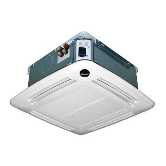
Page 8: Description Of The Unit
The cassette fan coils in the FCL range are available in two fundamental dimensions that are called "Modules" For two-pipe systems For four-pipe systems 8 sizes 7 sizes FCL 32 FCL 72 FCL 34 FCL 84 (Module 600) (Module 600) - Page 9 MAIN COMPONENTS 1 Grid with air filter 6 Base 11 Air vent valve 2 Receiver (GLL_M; GLL_R) 7 Fixing brackets 12 Semi-sliced, fitting for air flow to an 3 Air flow deflector 8 Electric box adjacent room 4 Grid frame 9 Hydraulic attachments (for 4 pipes only) 13 Condensate drain 5 Tray...
- Page 10 The electric motor with 3 speeds for simply coupling it to different grid smaller sizes (FCL 32-34-36-38) and units of the GLL series (mandatory 4 speeds for larger sizes, in order to accessory), which determine the...
- Page 11 INSTALLATION ATTENTION: before carrying out any The completion of all operations, accor- the best position of the fins is that that intervention, make sure that the elec- ding to specific requirements, is left to allows the launch of the air adhering to tric power supply has been disconnec- the experience of the installer.
- Page 12 - The grill frame must be positioned in appropriate brackets. a way that the AERMEC logo holder - Lift the unit carefully using the brackets corresponds with the corner of the and holding it slightly inclined. Fix it electric box.
- Page 13 "MODULE 600" INSTALLATION • INSTALLATION IN PROXIMITY OF A WALL If installed in proximity of a wall it is possible to close the corresponding flow inlet using the gasket supplied. IFCLIJ 1107 - 4528500_04...
- Page 14 - Remove the packaging shells used to - The grill frame must be positioned in protect the unit during transport. a way that the AERMEC logo holder - Apply the 4 installation brackets all’ corresponds with the corner of the unit.
- Page 15 - Remove the lock screw on the corner - Carry out the necessary maintenance. If the electric box must be accessed for door with the Aermec logo. - Re-mount everything performing the maintenance, follow the indications - Remove the 2 lock screws from the disassembly procedure in reverse order.
- Page 16 CONNECTIONS The water, condensate drainage and electrical circuit ducts must be provided for. HYDRAULIC CONNECTIONS The hydraulic attachments are with flat stroke 840x840 600x600 fittings complete with supplied gaskets. In the 4-pipe version of the unit, it is mandatory to install the hot water coil valve accessory.
- Page 17 ELECTRIC CONNECTIONS The unit must be connected directly magnet circuit breaker omnipolar appliance and the control panel. to an electrical outlet or to an switch on the power supply line with independent circuit. a minimum contact opening distance The FCL cassette fan coils must be of 3 mm.
- Page 18 INSTALLAZIONE E SOSTITUZIONE DEL FILTRO "Modulo 600" INSTALLATION AND REPLACEMENT OF THE "Module 600" FILTER INSTALLATION ET REMPLACEMENT DU FILTRE "Module 600" INSTALLATION UND AUSTAUSCH DES FILTERS "Modul 600" INSTALACIÓN Y SUSTITUCIÓN DEL FILTRO "Módul 600" PERICOLO: Togliere tensione prima d’iniziare le operazioni di pulizia del filtro e/o dell’unità. DANGER: Switch off power supply before cleaning filter and/or unit.
- Page 19 INSTALLAZIONE E SOSTITUZIONE DEL FILTRO "Modulo 840" INSTALLATION AND REPLACEMENT OF THE "Module 840" FILTER INSTALLATION ET REMPLACEMENT DU FILTRE "Module 840" INSTALLATION UND AUSTAUSCH DES FILTERS "Modul 840" INSTALACIÓN Y SUSTITUCIÓN DEL FILTRO "Módul 840" PERICOLO: Togliere tensione prima d’iniziare le operazioni di pulizia del filtro e/o dell’unità. DANGER: Switch off power supply before cleaning filter and/or unit.
-
Page 20: Table Of Contents
DATI DIMENSIONALI • DIMENSIONS • DONNÉES DES LES DIMENSIONS • ABMESSUNGEN • DATOS DIMENSIONALES [mm] FCL 32 FCL 34 FCL 36 FCL 38 FCL 42 FCL 44 GLL 10 FCL 62 GLL 10 R FCL 64 GLL 10 M FCL 72... -
Page 21: Dati Dimensionali • Dimensions • Données Des Les Dimensions • Abmessungen
DATI DIMENSIONALI • DIMENSIONS • DONNÉES DES LES DIMENSIONS • ABMESSUNGEN • DATOS DIMENSIONALES [mm] FCL 82 FCL 84 FCL 102 FCL 104 FCL 122 GLL 20 FCL 124 GLL 20 R GLL20 KFLD20 GLL20R KFLD20 KFL20 FCL_ [kg] FCL_V2 [kg] FCL_VL [kg]... - Page 22 SCHEMI ELETTRICI • WIRING DIAGRAMS • SCHEMAS ELECTRIQUES • SCHALTPLÄNE • ESQUEMAS ELÉCTRICOS LEGENDA • READING KEY • LEGENDE • LEGENDE • LEYENDA AL = Alimentatore PE = Collegamento a terra = Componenti non forniti Power supply GND Earth connection Components not supplied Alimentation electrique Mise à...
-
Page 23: Fcl 32
SCHEMI ELETTRICI • WIRING DIAGRAMS • SCHEMAS ELECTRIQUES • SCHALTPLÄNE • ESQUEMAS ELÉCTRICOS GLL10 / GLL20 + VHL1 / VHL2 + VHL20 / VHL22 VHL1 / VHL2 VHL20 / VHL22 VHL1 / VHL2 VHL20 / VHL22 Gli schemi elettrici sono soggetti ad un continuo aggiornamento, è obbligatorio quindi fare riferimento a quelli a bordo macchina. A l l w i r i n g d i a g r a m s... -
Page 24: Fcl_Vl
SCHEMI ELETTRICI • WIRING DIAGRAMS • SCHEMAS ELECTRIQUES • SCHALTPLÄNE • ESQUEMAS ELÉCTRICOS FCL VL GLL10 / GLL20 + VHL1 / VHL2 + VHL20 / VHL22 VHL1 / VHL2 VHL20 / VHL22 VHL1 / VHL2 VHL20 / VHL22 Gli schemi elettrici sono soggetti ad un continuo aggiornamento, è obbligatorio quindi fare riferimento a quelli a bordo macchina. A l l w i r i n g d i a g r a m s... -
Page 25: Fcl
SCHEMI ELETTRICI • WIRING DIAGRAMS • SCHEMAS ELECTRIQUES • SCHALTPLÄNE • ESQUEMAS ELÉCTRICOS GLL10M + VHL1 / VHL2 + RXLE + SW 00-NC RXLE Gli schemi elettrici sono soggetti ad un continuo aggiornamento, è obbligatorio quindi fare riferimento a quelli a bordo macchina. A l l w i r i n g d i a g r a m s... - Page 26 SCHEMI ELETTRICI • WIRING DIAGRAMS • SCHEMAS ELECTRIQUES • SCHALTPLÄNE • ESQUEMAS ELÉCTRICOS GLL10R + VHL1 / VHL2 + RXLE + SW 00-NC RXLE Gli schemi elettrici sono soggetti ad un continuo aggiornamento, è obbligatorio quindi fare riferimento a quelli a bordo macchina. A l l w i r i n g d i a g r a m s...
-
Page 27: Fcl
SCHEMI ELETTRICI • WIRING DIAGRAMS • SCHEMAS ELECTRIQUES • SCHALTPLÄNE • ESQUEMAS ELÉCTRICOS GLL10 / GLL20 WMT10 + VHL1 / VHL2 + VHL20 / VHL22 VHL1 VHL2 VHL20 VHL22 GLL10 / GLL20 PXAE + VHL1 / VHL2 + VHL20 / VHL22 + SW VHL1 VHL2... -
Page 28: Fcl
SCHEMI ELETTRICI • WIRING DIAGRAMS • SCHEMAS ELECTRIQUES • SCHALTPLÄNE • ESQUEMAS ELÉCTRICOS GLL10 / GLL20 FMT10 + VHL1 / VHL2 + VHL20 / VHL22 VHL1 VHL2 VHL20 VHL22 GLL10 /GLL20 FMT20AW + VHL1 / VHL2 + VHL20 / VHL22 VHL1 VHL2 VHL20... -
Page 29: Fcl
SCHEMI ELETTRICI • WIRING DIAGRAMS • SCHEMAS ELECTRIQUES • SCHALTPLÄNE • ESQUEMAS ELÉCTRICOS GLL10N / GLL20N 230V 50Hz VMF-SW1 Power Dip Switch Supply GLL10N GLL20N TX/RX GND-TTL MODE TX/RX CN CN VHL1 Dis.4818570_00 Gli schemi elettrici sono soggetti ad un continuo aggiornamento, è obbligatorio quindi fare riferimento a quelli a bordo macchina. A l l w i r i n g d i a g r a m s... -
Page 30: Fcl
SCHEMI ELETTRICI • WIRING DIAGRAMS • SCHEMAS ELECTRIQUES • SCHALTPLÄNE • ESQUEMAS ELÉCTRICOS ATTENZIONE: Spostare il terminale del fi lo marrone singolo dal morsetto 5 al morsetto 6 WARNING: Move the end of the individual GLL10 brown wire from clamp 5 to clamp 6 GLL20 ATTENTION: Déplacer l'extrémité... -
Page 31: Ifclij 1107 - 4528500_04
AERMEC S.p.A. si riserva la facoltà di apportare in qualsiasi momento tutte le modifiche ritenute necessarie per il miglioramento del prodotto. Les données mentionnées dans ce manuel ne constituent aucun engagement de notre part. Aermec S.p.A. se réserve le droit de modifier à tous moments les données considérées nécessaires à...
Need help?
Do you have a question about the FCL 32 and is the answer not in the manual?
Questions and answers