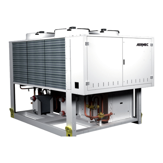
AERMEC NRP 0800 Technical Installation Manual
Multipurpose units for 2/4-pipe systems, outdoor unit, high efficiencies
Hide thumbs
Also See for NRP 0800:
- Installation manual (36 pages) ,
- Technical manual (32 pages) ,
- Installation manual (44 pages)

Subscribe to Our Youtube Channel
Related Manuals for AERMEC NRP 0800


Summary of Contents for AERMEC NRP 0800
- Page 1 MULTIPURPOSE UNITS FOR 2|4-PIPE SYSTEMS - Technical installa on manual MULTIPURPOSE UNIT NRP 0800-1800 • OUTDOOR UNIT • HIGH EFFICIENCIES INRPPY.12.02.5806765_00...
- Page 2 AERMEC S.p.A AERMEC S.p.A. reserves the right to make any modifications considered necessary to improve its products at any moment and is not obliged to add these modifications to machines that have already been manufactured, delivered or are under construction.
-
Page 3: Table Of Contents
NRP 0800 ÷ 1000 minimum technical spaces ....... 31 4.2. Hot water produc on only to system ..........11 24.3. NRP 0800 ÷ 1000 hydraulic connec ons posi on vers. 00 ..... 31 4.3. Simultaneous hot and cold water produc on to system ....11 24.2. - Page 4 NRP 0800-1800 Aermec code 5806765_00 12.02...
-
Page 5: Declaration Of Conformity
The product, in agreement with Directive 97/23/EC, satisfies the Total quality Guarantee procedure (form H) with certificate no. 06/270-QT3664 Rev. 6 issued by the notified body n.1131 CEC via Pisacane 46 Legnano (MI) - Italy The person authorised to draw-up the technical file is: Massimiliano Sfragara - 37040 Bavilacqua (VR) Italy - Roma, 996 Bevilacqua 09/01/2012 Marketing Manager Signature Aermec code 5806765_00 12.02... -
Page 6: Descrip On Of The Unit
It automatically changes from one configuration to the other (managed by on-board microprocessor) to optimise the energy spent depending on the demand Aermec code 5806765_00 12.02... -
Page 7: Configurator
R4 High head pressure pump | reserve pump | DHW side DHW SIDE/SYSTEM SIDE DHW side, production of domestic hot water, in 2-pipe systems. System side, production of hot water, in 4-pipe systems. Reading key The configuration desired must be na Not available specified when ordering Aermec code 5806765_00 12.02... -
Page 8: Basic Opera Ng Layouts For 2-Pipe System
LPT Low pressure transducer not running exchanger AL Liquid storage tank LS Liquid separator SOURCE SIDE heat (EVAPORATION) CV One-way valve TEV Thermostatic valves exchanger Heat exchange with air F Dehydrator filter VIC Cycle reversing valves Aermec code 5806765_00 12.02... -
Page 9: Circuits To Produce Hot Water Only To Dhw
DHW SIDE heat ex- (CONDENSATION) Source side heat exchanger Low pressure transducer changer DHW production Liquid storage tank Liquid separator SOURCE SIDE heat One-way valve TEV Thermostatic valves Not running exchanger Dehydrator filter Cycle reversing valves Aermec code 5806765_00 12.02... -
Page 10: Circuit For Producing Hot Water To System | Circuit For Producing Hot Water To Dhw
SOURCE SIDE heat ex- (CONDENSATION) 3 Source side heat exchanger LPT Low pressure transducer changer Heat exchange with air AL Liquid storage tank LS Liquid separator CV One-way valve TEV Thermostatic valves F Dehydrator filter VIC Cycle reversing valves Aermec code 5806765_00 12.02... -
Page 11: Hot Water Produc On Only To System
HEATING SIDE heat (CONDENSATION) Source side heat exchanger Low pressure transducer exchanger hot water production Liquid storage tank Liquid separator SOURCE SIDE heat One-way valve TEV Thermostatic valves Not running exchanger Dehydrator filter Cycle reversing valves Aermec code 5806765_00 12.02... -
Page 12: Descrip On Of Components
As per standard As per standard Air vent valve As per standard As per standard As per standard As per standard Expansion vessels (2x25 l) As per standard As per standard As per standard As per standard Aermec code 5806765_00 12.02... -
Page 13: Water Features
5.5. ELECTRIC CONTROL BOARD Electric control board incompliance with EN 60204-1/ IEC 204-1 Standards, complete with: - transformer for the control circuit, - door lock main isolating switch, - fuses and contactors for compressors and fans, Aermec code 5806765_00 12.02... -
Page 14: Accessories
• • • • • • • • AERWEB300-18 • • • • • • • • AERWEB300-6G • • • • • • • • AERWEB300-18G ALL • • • • • • • • Aermec code 5806765_00 12.02... -
Page 15: Technical Data
External air temperature 35 °C External air temperature 7°C d.b. 6°C w.b. Δt water 5°C DHW SIDE/SYSTEM SIDE DHW side, production of domestic hot water, in 2-pipe systems. System side, production of hot water, in 4-pipe systems. Aermec code 5806765_00 12.02... - Page 16 14.4 14.4 21.6 21.6 21.6 28.8 28.8 10.2 10.2 10.2 13.6 13.6 Input power when cold 10.2 10.2 10.2 13.6 13.6 Input power when hot 10.2 10.2 10.2 13.6 13.6 INVERTER AXIAL FANS -J- Static pressure Aermec code 5806765_00 12.02...
-
Page 17: Cooling Mode Operation
3950 4090 Sound power Sound pressure Aermec determines sound power values on the basis Sound pressure in free field conditions on reflective of measurements made in compliance with the 9614-2 surface (directivity factor Q=2) at 10 mt from the Standard, in agreement with that requested by Eurov- external surface of unit, in compliance with ISO 3744 ent certification. -
Page 18: Opera Onal Limits
To shorten this operation, it is recommended to can be started with external air -15°C and inlet install a three-way valve, which makes it possible water 20°C. to by-pass the water from the utilities to the system, until achieving conditions that allow the Aermec code 5806765_00 12.02... -
Page 19: Correc On Factors For Data Diff Erent To Nominal In Cooling Mode
ΔT WATER DIFFERENT TO NOMINAL ΔT 5°C Cooling capacity correction factors 0,99 1,02 1,03 Input power correction factors 0,99 1,01 1,02 DEPOSIT FACTORS [K*m2]/[W] 0,00005 0,0001 0,0002 Cooling capacity correction factors 0,98 0,94 Input power correction factors 0,98 0,95 Aermec code 5806765_00 12.02... -
Page 20: Yields And Absorp On Diff Erent To Nominal
45 °C 40 °C 35 °C Temperature of the water produced (°C) AT THE EVAPORATOR ΔT WATER DIFFERENT TO NOMINAL ΔT 5°C Heating capacity correction factors 0,99 1,01 1,02 Input power correction factors 1,01 0,98 0,96 Aermec code 5806765_00 12.02... -
Page 21: Total Pressure Drops 2|4 Pipe Units
10° C NRP1400 NRP1500 For temperatures other than 43°C, use the correction factors table NRP1650 NRP1800 50000 100000 150000 200000 Water flow rate l/h Average water temperature Multiplicative coefficient 1.04 1.03 1.02 1.01 1.00 0.99 0.98 0.97 Aermec code 5806765_00 12.02... -
Page 22: Useful Head Pressures 2|4-Pipe System
Water flow rate l/h 13.4. DHW SIDE HIGH HEAD PRESSURE PUMPS 2 PIPES | HEATING SIDE 4 PIPES 0800 0900 1000 1250 1400 1500 1650 1800 20000 40000 60000 80000 100000 120000 140000 160000 Water flow rate l/h Aermec code 5806765_00 12.02... -
Page 23: Ethylene Glycol Solution
Remember that the initial “EXTERNAL AIR TEM PERATURE” and “TEMPERATURE OF PRODUCED WATER” values are not directly related, therefore it is not possible to refer to the curve of one of these values and obtain corresponding point on the other curve. Aermec code 5806765_00 12.02... -
Page 24: 14.1.1. Expansion Vessel Calibra On
It is recommended to design systems with high water content (minimum recommended values shown in table), in order to limit: 1. The hourly number of inversions between operating modes. 2. Drop in water temperature during winter defrost cycles. Aermec code 5806765_00 12.02... -
Page 25: Input Power
1650 1800 HEATING CAPACITY % 1° 2° 3° 4° 5° 6° 0800 0900 1000 1250 1400 1500 1650 1800 INPUT POWER % 1° 2° 3° 4° 5° 6° 0800 0900 1000 1250 1400 1500 1650 1800 Aermec code 5806765_00 12.02... -
Page 26: Sound Data
10 m STANDARD fans! COOLING MODE OPERATION 0800 64.5 96.5 75.5 0900 64.5 96.5 75.5 Sound power Aermec determines sound power values on the 1000 83,5 51.5 82.7 78.6 74.2 73.3 69.3 65.4 basis of measurements made in compliance with 1250 67.5... -
Page 27: Calibra Ons Of Safety And Control Parameters
MTC1B MTC2 MTC2A MTC2B MANUAL RESET HIGH PRESSURE SWITCH HIGH PRESSURE TRANSDUCER LOW PRESSURE TRANSDUCER COOLING CIRCUIT SAFETY VALVES FANS MAGNET-CIRCUIT BREAKERS - Calibra on is performed on 2 magnet-circuit breakers (2 ven la on lines) Aermec code 5806765_00 12.02... -
Page 28: General Warnings
(Ministerial Decree 329/2004). tion to be performed difficult. AERMEC will not assume any liability for damage if these instructions are not respected. Aermec code 5806765_00 12.02... -
Page 29: Receipt Of The Product And Installa On
Whenever the machine must be lifted using belts, place protections between the belts and the frame- work to prevent damage to the structure. NRP 0800-1800 units are supplied with eyebolts; they must be lifted using suitable belts hooked to all the installed eyebolts. -
Page 30: Weights And Barycentres
NRP 0800-1800 WEIGHTS AND BARYCENTRES VIEWS FROM ABOVE TAB.1 WEIGHT OF UNITS WHEN EMPTY NRP 0800 - 0900 - 1000 WEIGHT DISTRIBUTION ON BARYCENTRE SUPPORTS (%) (mm) 3400 1400 1400 0800 2270 1331 821 11.2% 18.8% 19.5% 32.7% 6.7% 11.2% 0900 2460 1374 794 10.1% 17.9% 19.1% 33.8% 6.9% 12.2%... -
Page 31: Dimensions | Hydraulic Connec Ons
3000 3400 2200 24.2. NRP0800 ÷ 1000 HYDRAULIC CONNECTIONS POSITION vers. P1...P4|R1...R4 DHW side / heating system side pumps unit Ø 3” VICTAULIC CONNECTIONS Coling / heating system side pumps unit Ø 3” VICTAULIC CONNECTIONS 1300 Aermec code 5806765_00 12.02... -
Page 32: Nrp 1250 Minimum Technical Spaces
Ø 4” VICTAULIC CONNECTIONS 24.6. NRP 1250 HYDRAULIC CONNECTIONS POSITION vers. P1...P4|R1...R4 DHW side / heating system side pumps unit Ø 4” VICTAULIC CONNECTIONS Coling / heating system side pumps unit Ø 4” VICTAULIC CONNECTIONS 1806 Aermec code 5806765_00 12.02... -
Page 33: Nrp 1400 1500 Minimum Technical Spaces
Ø 4” VICTAULIC CONNECTIONS 24.9. NRP 1400 1500 HYDRAULIC CONNECTIONS POSITION vers. P1...P4|R1...R4 DHW side / heating system side pumps unit Ø 4” VICTAULIC CONNECTIONS Coling / heating system side pumps unit Ø 4” VICTAULIC CONNECTIONS 1806 Aermec code 5806765_00 12.02... -
Page 34: 24.10. Nrp 1650 1800 Minimum Technical Spaces
Cooling and heating system side 5750 exchanger Ø 4” VICTAULIC CONNECTIONS 24.12. NRP 1650 1800 HYDRAULIC CONNECTIONS POSITION vers. P1...P4|R1...R4 DHW side /heating system side exchanger Ø 4” VICTAULIC CONNECTIONS Cooling and heating system side exchanger Ø 4” VICTAULIC CONNECTIONS Aermec code 5806765_00 12.02... -
Page 35: Basic 2-Pipe System Hydraulic Circuits
Less than 0.3 ppm 2. Drop in water temperature Alkalinity M Less than 50 ppm during winter defrost cycles. Total hardness Less than 50 ppm Sulphur ions none Ammonia ions None Silicone ions Less than 30 ppm Aermec code 5806765_00 12.02... -
Page 36: Hydraulic Circuit Inside And Outside Nrp Version "With P1
Total iron Less than 0.3 ppm Alkalinity M Less than 50 ppm Total hardness Less than 50 ppm Sulphur ions none Ammonia ions None DHW SIDE SYSTEM SIDE Silicone ions Less than 30 ppm Aermec code 5806765_00 12.02... -
Page 37: Basic 4-Pipe System Hydraulic Circuits
Sulphuric acid ions Less than 50 ppm Total iron Less than 0.3 ppm Alkalinity M Less than 50 ppm Total hardness Less than 50 ppm Sulphur ions none Ammonia ions None Silicone ions Less than 30 ppm Aermec code 5806765_00 12.02... -
Page 38: Hydraulic Circuit Inside And Outside The Nrp "P1
Less than 0.3 ppm during winter defrost cycles. Alkalinity M Less than 50 ppm Total hardness Less than 50 ppm Sulphur ions none DHW SIDE SYSTEM SIDE Ammonia ions None Silicone ions Less than 30 ppm Aermec code 5806765_00 12.02... -
Page 39: System Loading
Open the drain cock outside the appliance and It should be collected and if all system and relative terminals vent valves possible reused. Aermec code 5806765_00 12.02... -
Page 40: Electric Connec Ons
Maximum input power 3+N: 3 phases + neutral F.L.A.: Maximum input current Sec B: Controls and safety device connection L.R.A.: Initial starting current EARTH: Earth wire to connect to unit Sec A: Power supply Master switch Aermec code 5806765_00 12.02... -
Page 41: Prepara On For Commissioning
Check that the connections made by the installer in this series can be started up by the AERMEC are in compliance with the documentation. A er-Sales Service in your area (valid only on Italian Verify that the compressor sump resistance/s is/ territory). -
Page 42: Opera Ng Features
The pump side u li es start immediately. A er the fi rst 30 seconds of opera ng, when the water fl ow rate has Aermec code 5806765_00 12.02... -
Page 43: Switch-On And Use Of Unit
Only qualified staff can change the language by accessing the assistance menu When 20 seconds have passed, it will no longer be possible to modify the language until the next time the board is restarted. MENU STRUCTURE Aermec code 5806765_00 12.02... -
Page 44: Accessory Connec Ons
I/ O prog. on/offalar m enter KIT PGD1 max 50 m (ACCESSORY) Telephone cable cavo telefonico I/ O prog. on/offalar m enter Telephone cable S90CONN*: cavo di collegame nto Field-Bus Field-Bus μPc RS485P1 serial board (ACCESSORY) Aermec code 5806765_00 12.02... - Page 45 • Adjust or replace if damaged • Thermostatic expansion valve damaged or blocked • Check: Low intake pressure 1. Fan operation • Insufficient water flow 2. Cleanliness of the coils • Insufficient air flow 3. Pump operation (speed) 4. Filter cleanliness Aermec code 5806765_00 12.02...
- Page 46 NRP 0800-1800 Aermec code 5806765_00 12.02...
- Page 47 NRP 0800-1800 Aermec code 5806765_00 12.02...
- Page 48 37040 Bevilacqua (VR) Italy–Via Roma, 996 Tel. (+39) 0442 633111 Telefax 0442 93730–(+39) 0442 93566 www.aermec.com - info@aermec.com The technical data given in this documentation is not binding. Aermec reserves the right to make all modifications deemed necessary for improving the product at any time.
Need help?
Do you have a question about the NRP 0800 and is the answer not in the manual?
Questions and answers