Advertisement
Quick Links
Advertisement

Related Manuals for AERMEC FCL Series


Summary of Contents for AERMEC FCL Series
- Page 1 AFTER-SALES SERVICE TECHNICAL MANUAL New cassette series fan coil...
- Page 2 FCL - FAN COIL The FCL cassette-type fan coil: 4 sizes for 2-pipe systems FCL 32 - FCL 36 - FCL 42 - FCL 62 4 sizes for 4-pipe systems FCL 34 - FCL 38 - FCL 44 - FCL 64 VERSIONS The cassette fan coils are available in three versions, to satisfy all system requirements.
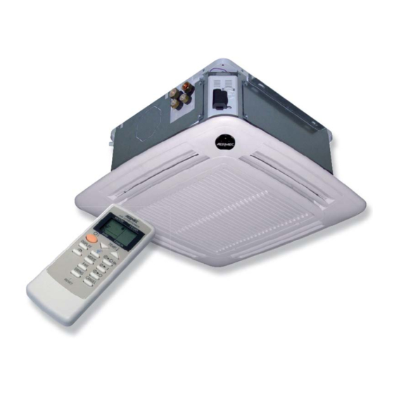
- Page 3 - GLL 10 M: with remote control, louvres oriented by the remote control, IR receiver integrated in the grille. GLL-M is complete with an electronic thermostat able to manage all the configurations (heating coil with valve, cooling coil with valve, supplementary or replacement electric heater) as well as all the functions (heating, cooling, continuous or thermostat-operated ventilation, dehumidification, timed switch-on or switch-off operations).
-
Page 4: Main Components
Main customisations envisaged: - electric heater for heating (accessories RXL and RXLE) - supplementary or replacement, they can be installed in 2- or 4-pipe units - 3-way valve for heating coils for 4-pipe systems (accessory VHL1) - 2-way valve for heating coils for 4-pipe systems with variable water flow rate (accessory VHL2) - connection flange for delivery air conduit towards a second nozzle, even in an adjacent room (accessory KFL) - connection flange for external fresh air conduit, even with the fan switched off (accessory KFLD) -
Page 5: Description Of The Components
DESCRIPTION OF THE COMPONENTS Base The unit is characterised by a reinforced, integral metal structure with insulation expanded polystyrene obtained from injection moulding for purposes of noise reduction and air routing. The load- bearing base is in galvanised sheet steel varnished with polyester powders. - Page 6 Basin Basin closing off the unit. Made of injection co-moulded polystyrene to avoid thermal dispersion and the formation of condensate, it conveys conditioned air towards the louvres from condensate drip basin. The intake conveyor equipped with a protective grille that impedes access to the moving fan.
- Page 7 Three-way valve Internal 3-way valve, of the all-or-nothing type, with fast connection actuator visual signalling position, assembled standard heating/cooling coil, powered with a voltage of 230V ~ 50Hz.
- Page 8 Fan unit The fan unit, with the latest axial-centrifugal fan designed obtain sound emissions, is dynamically and statically balanced coupled with 4-speed motor. The fan unit can be easily accessed for cleaning and maintenance.
- Page 9 Motor for FCL 32- 34- 36- 38...
- Page 11 Motor for FCL 42- 44...
- Page 12 Motor for FCL 62- 64...
- Page 13 Condensate discharge device The condensate discharge device disposes of the condensate that is produced by the unit and deposited in the polystyrene basin. The device consists of a control card, a non-return valve, a 3-level float and a pump with a maximum pressure of 800mm. The unit can be easily connected to the condensate discharge system by means of a plastic connector with an external Ø...
- Page 14 Attachment plate The attachment plate groups together the plumbing connections and the vent of the coil's primary circuit for 2-pipe and 4-pipe systems. The plates contain raised symbols that identify the input (IN) and output (OUT) plumbing connections for the water.
- Page 15 Intake and delivery grille unit The grille is part of the GLL range unit (obligatory accessory). The form and opening of the intake slats were developed in order to have the best possible distribution of the air, both when functioning in winter as well as in summer. Suction is made via the central grille, and delivery via the perimeter openings that can be manually oriented (or, only for version GLL10M, by means of the remote control).
- Page 16 Electric box The electric box is part of the grill unit and is inserted with bayonet coupling in the connector bound to the unit's load-bearing structure.
- Page 17 Sizes and weights...
-
Page 18: Technical Data
TECHNICAL DATA... - Page 19 Operating limits Sound pressure level ACCESSORIES Obligatory accessories Grilles of the GLL range are obligatory accessories as the FCL units are supplied without them GLL M (RAL 9010) Air delivery and pick-up grille. Louvres oriented by the remote control and electronic control, IR receiver integrated in the grille.
- Page 20 Accessories Kit composed of a 100mm metal flange that sends the air into an adjacent room. KFLD Kit composed of a 100mm metal flange and a bulkhead in galvanised and insulated steel sheet. KFLD allows external air intake to be directly released into the room without being mixed. Electric heater for heating, can be installed on FCL units.
- Page 21 FMT10 FLUSH-MOUNTING CONTROL PANEL WITH ELECTRONIC THERMOSTAT Electronic thermostat for fan coils installed in systems with 4 pipes, 2 pipes and 2 pipes with heater, with the possibility of connecting two On - Off valves to shut off the water feeding the coils. Commands simplified with only two selectors for temperature and ventilation control (3 speeds).
- Page 25 Installation information WARNING: before carrying out any interventions, make sure the power supply has been cut off. WARNING: before carrying out any interventions, adopt the proper personal protective equipment. WARNING: the appliance must be installed according to the national plant engineering regulations. WARNING: the electrical connections, the installation of the fan coils and relevant accessories should be performed by a technician who has the necessary technical and professional expertise to install, modify, extend and maintain systems, and who is able to check the systems for the...
-
Page 26: Plumbing Connections
CONNECTIONS PLUMBING CONNECTIONS The plumbing connections are made with flat fittings complete with seal gaskets (supplied). In the 4-pipe version of the unit, it is essential to install the VHL1 valve accessory. For this purpose use the supplied gaskets. The accessory has gaskets for connection to the system. Information for the correct installation of the VHL1 valve is contained in the accessory instruction booklet. -
Page 27: Condensate Discharge Connection
CONDENSATE DISCHARGE CONNECTION During cold functioning the indoor unit removes humidity from the air. The condensate water must be eliminated by connecting the appropriate discharge coupling to the piping of the condensate discharge system. The polystyrene basin has a hole permitting the condensate to be fully run off (this is also useful in the event of disassembly). - Page 28 CONNECTIONS FOR THE DELIVERY OF TREATED AIR TO AN ADJACENT ROOM The unit can be connected to a conduit (diameter 100mm) for delivering treated air to an adjacent room via the circular KFL flange accessory. The application of the flange requires a hole to be opened up on the side.
-
Page 29: Electrical Wirings
CONNECTIONS FOR THE INTAKE OF FRESH EXTERNAL AIR The unit can be connected to a fresh air intake conduit via the circular KFLD flange accessory (diameter 100mm), applied to the vent. The application of the flange requires a hole to be opened up on the side. -
Page 33: Wiring Diagrams
WIRING DIAGRAMS AL = Power supply CE – EX = External contact CN = Connector CRE = Electric heater contactor F = Fuse IG = Master switch M = Control board ML = Louvre motor MV = Fan motor NC – 00 = Not connected PE –... - Page 35 Wiring diagrams are constantly updated. It is therefore compulsory to refer to the ones supplied with the unit.
- Page 36 Wiring diagrams are constantly updated. It is therefore compulsory to refer to the ones supplied with the unit.
- Page 37 Wiring diagrams are constantly updated. It is therefore compulsory to refer to the ones supplied with the unit.
- Page 38 Wiring diagrams are constantly updated. It is therefore compulsory to refer to the ones supplied with the unit.
- Page 39 Wiring diagrams are constantly updated. It is therefore compulsory to refer to the ones supplied with the unit. Wiring diagrams are constantly updated. It is therefore compulsory to refer to the ones supplied with the unit.
- Page 40 Wiring diagrams are constantly updated. It is therefore compulsory to refer to the ones supplied with the unit.
- Page 41 Wiring diagrams are constantly updated. It is therefore compulsory to refer to the ones supplied with the unit.
-
Page 42: Electronic Adjustment
ELECTRONIC ADJUSTMENT The card for commanding the cassette is shown below, with an indication of the outputs S2: sonda batteria (acqua o gas) S1: sonda ambiente SW1: dip s witc h 1, da 8 di p S4: NTC resistenza C1: contatto esterno S3: seconda NTC o sonda SW2: dip switch 1, da 8 dip acqua... - Page 43 control card input/output FCL hydronic cassette Type Electrical characteristics (twin/single) CN1: connector for 4-LED Rapido Connector for 4-LED receiver (on the unit) receiver (on the unit) Potential-free Faston. Used to support 4-speed Faston 6.35mm V0: output not used motors. V1: minimum fan speed Faston 6.35mm Output: voltage 230V AC, current 5 A (Relay) output...
- Page 44 Types of machine The configuration of the cassette machines in fan coil mode is shown below. Cassette fan coil (FCL) From the control point of view, the machine logic involved can be traced to the cases indicated in the figures, and are the 2-pipe and 4-pipe cassettes and those with supplementary or replacement electric heater and any water control probe up line or down line from the valve.
- Page 45 2-pipe fan coil, with supplementary/replacement electric heater with water probe (optional) only up line from the valve Key: SA Ambient probe SW Water probe RXL Electric heater VHL Solenoid valve (Hot/Cold) 4-pipe fan coil, with electric heater and hot water probe (optional) only up line from the valve Key: SA Ambient probe...
- Page 46 Using the system This section shows the selection of the functioning mode by the user via remote control, and the configuration of the system by the manufacturer and installer by means of dip switches. Compatibility of remote controls The table shows the compatibility between remote controls and board codes and replacements: CRMC- A698JBEZ CRMC- A360JBEO (old) (new)
- Page 47 Emergency setting and receiver visualisations If necessary there is an “AUX” key on the grille receiver, that activates the "Auto- Emergency" mode. In this mode, the machine functions automatically dependent on the ambient temperature read the moment the AUX key is pressed.
- Page 48 Setting the dip-switches on the board. The microprocessor of the board recognises the type of machine from the way the dip-switches are set. The configurations that can be set are: FCL cassette-type fan coil FCL cassette-type twin fan coil It is also possible to configure machines ECL, EXC, CUCCIOLO, EXM, ANCX, but this procedure lies outside the scope of this document.
- Page 49 Meaning of the dip-switches in the fan coil (FCL) configuration With dip-switches 3, 6, 8 of SW2 in FCL configuration, the dip-switches SW1 and SW2 assume this meaning. The meaning of the SW2 dip-switch Resistenza in integrazione Normale 2 tubi Libero Sonda acqua sulla batteria Ventilazione continua...
- Page 50 The meaning of the SW2 dip-switch Normale Libero Tipo macchina Libero Ricevitore a bordo macchina Tipo macchina Normale Tipo macchina DIP SW2 Tipo macchina AL1 usato come allarme se chiuso Tipo macchina Ricevitore a parete Libero Tipo macchina Libero Autotest per collaudo HW DIP1 not used DIP2 not used DIP3 decides kind of unit...
- Page 51 Control logics Cooling mode (fan coil) By means of the remote control it is possible to set the cooling mode and set an operating temperature. If the fan speed is set in automatic mode the system selects the fan speed for itself and decides the opening of the water valve depending on the difference between the operating temperature set by the user (setting) and the temperature measured by the ambient probe.
- Page 52 In the case of the 4-pipe configuration, in the cooling mode, the control board rather than the generic solenoid valve VS, will control the cooling solenoid valve VSF (shown in brackets in the diagrams above) while the heating solenoid valve (VSC) is closed. Heating mode (fan coil) By means of the remote control it is possible to set the heating mode and a reference temperature.
- Page 53 In the 2-pipe configuration the heating mode is activated by controlling the general solenoid valve Y1, while in the 4-pipe configuration the heating water solenoid valve Y2 is controlled with the same logic, and closing the cooling water valve (that in the 4-pipe case is Y1) as soon as the heating mode is imposed.
- Page 54 Motorised louvre From the remote control, the swing key will put the louvre into motion and this will continue to rotate until the next (stop) command. The louvre also stops when the ventilation stops (e.g. because the setting has been reached). Ambient probe The reading of the temperature by means of the ambient probe is continuous with the ventilation in operation.
- Page 55 Thermostat-controlled heating ventilation: pre-heating of electric heater . electric heater used (whether as a supplement or replacement) the timing takes into account the need to prevent the electric heater remaining at high temperatures for too long. When the electric heater is turned on, a pre-heating phase begins (30 seconds at V ) before arriving at full capacity.
- Page 56 Water control (optional) It is possible for a probe (SW 4) to be installed for reading the temperature of the water circulating in the exchange coils. Below there is a detailed description of a control logic for enabling/disabling the loads on the basis of the temperature read by the water probe and the functioning mode set from the remote control.
- Page 57 Auto functioning (from the remote control) In this functioning mode the user does not set the temperature; the fan of the indoor unit functions in Automatic mode. By activating the "AUTO" mode on the remote control, the temperature SET disappears and the fan works in automatic mode.
- Page 58 Autotest This section shows the two autotest procedures: from infrared receiver and wired panel. It is possible to activate the autotest mode by powering the machine, keeping the AUX key pressed down for about 5 seconds. In this case, the board makes two beeps by means of the buzzer, and is positioned at step 0.
- Page 59 Alarm management The management of the alarm situations will be as follows: When an anomaly arises the machine will be put in stop status (Pre-alarm) and the anomaly is counted. There are two possible situations at this point: the pre-alarm remains for a time in excess of the maximum value (Time-out): in this case the alarm is taken to the Alarm state definitively.
-
Page 60: Alarm Display
Alarm log display It is also possible to display the last anomalies that arose and were automatically reset. For all the receivers, the procedure is as follows: place the machine in standby and press the AUX key for at least 5 seconds (a triple beep indicates that this function is being used). - Page 61 Probe display (with infrared receiver) It is possible to display the values of the temperature probes captured by the electronic board. To do this it is necessary to follow the following procedure: set OFF from the remote control (or by pressing the AUX key). press the AUX key for 5s.
- Page 62 Reference standards The following standards have been complied with: Safety CEI EN 60335-1 CEI EN 60335-2-40 <Tab/>Electromagnetic compatibility CEI EN 50081-1 CEI EN 50082-1...
- Page 63 FCL - FAN COIL _______________________________________________________________ 2 VERSIONS ____________________________________________________________________ 2 DESCRIPTION OF THE FCL CASSETTE-TYPE FAN COILS _________________________ 2 DESCRIPTION OF THE COMPONENTS __________________________________________ 5 TECHNICAL DATA____________________________________________________________ 18 ACCESSORIES _______________________________________________________________ 19 CONNECTIONS _______________________________________________________________ 26 WIRING DIAGRAMS __________________________________________________________ 33 ELECTRONIC ADJUSTMENT __________________________________________________ 42...
Need help?
Do you have a question about the FCL Series and is the answer not in the manual?
Questions and answers