
Related Manuals for AERMEC RTE240


Summary of Contents for AERMEC RTE240
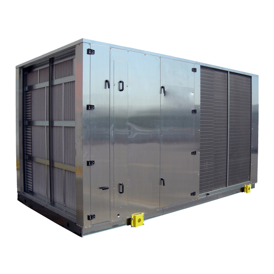
- Page 1 ROOF-TOP UNITS R410A - Manual selection, installation and maintenence 240-400 1102. 6180892_00...
- Page 2 AERMEC S.p.A. 37040 Bevilacqua (VR) – Italy Via Roma, 996 Tel. (+39) 0442 633111 www .aermec. com 1115 DICHIARAZIONE DI CONFORMITA’ DECLARATION OF CONFORMITY DÉCLARATION DE CONFORMITÉ KONFORMITÄTSERKLÄRUNG Tipo macchina / Type of unit / Type Condizionatore d'aria tipo Roof-top, Roof-top air conditioning unit de machine / Maschinentyp Unité...
-
Page 3: Table Of Contents
Index General norm Units identification and description Version cambination Unit configuration Description of components Regulation system Accessories Technical data Operating limits Sound data Cooling capacity and input power Heating capacity and input power Corrective coefficients for different flow rates Total capacities for different relative humidities Performance tables for water heating coils Technical data generator Gxxx List of pressure equipment - Directive PED 97/23 CE... -
Page 4: General Norm
G E N E R A L P R O H I B I T I O N to machines of previous manufacture • AERMEC S.p.A. declines all liability SIGNAL that have already been delivered or are... -
Page 5: Units Identification And Description
For any future reference and for all SMP : rooftop with 2-way mixing box rear communication with the AERMEC SpA must indicate the number. In addition, each piece is accompanied by targhettta with weight and other information traceability. - Page 6 Roof-top units - RTE series- Version combinations Version combinations SM2-FT7: rooftop with 2-way mixing box, side/bottom exhaust and bag filters F7 (fig.5) G72-SMP: rooftop with 72kW heat generator and 2-way mixing box rear exhaust (fig.8) (1)(2) G72-FT7: rooftop with 72 kW heat generator and bag filters F7 (fig.9) G92-SMP: rooftop with 92kW heat generator and 2-way mixing box rear...
-
Page 7: Unit Configuration
Roof-top units - RTE series- Unit configuration Field 1, 2, 3,4 Field 5, 6, 7 Field 8 Versions cooling only heat pump Field 9 Operation Standard Low-noise operation (no 350 and 400) High temperature (no 350 and 400) Field 10 Power supply °... - Page 8 Roof-top units - RTE series- Field 12 Filter pressure switch /coil protection grille accessory ° No accessory of the PF/GP type Heat recovery unit with by-pass (option only valid if field 10 = P, Q, V, Y, Z, X, W, O) Filter pressure switch Condenser protection grille PF+GP...
- Page 9 Roof-top units - RTE series- Field 17 Refrigeration circuit accessories ° No refrigeration circuit accessory DCPR Low temperature device (external temperature down to - 20 °C) (standard on the low noise operation units) Pressure transducers (standard in the heat pump version) Discharge and Liquid shut-off valves (for cooling only version) DCPR+TP DCPR+RUB...
-
Page 10: Description Of Components
Roof-top units - RTE series- Description of components Refrigeration circuit Compressors Scroll-type hermetic compressors with crankcase heater provided as a standard in the heat pump version (and in the only coolung version, if provided with DCPR accessory) Provided the unit is under voltage the heating element is automatically switches on when the unit stops. -
Page 11: Regulation System
Roof-top units - RTE series- Regulation system The architecture of the microprocessor control (fig. 02) provides for: • a BASE CARD with microprocessor dedicated to the execution of the control program, provided with display, keyboard and LED to allow for the programming of the set-points and the basic user operations (on/off, display of checked values, optional print-out ). -
Page 12: Accessories
Roof-top units - RTE series- Accessories DCPR - Pressure switch control device BTR- Two-row heating coil PR2 - Remote panel Extends the operating range of the rooftop, Two-row hot water coil with three way This enables rooftop control operations to be both in the summer cycle (minimum outside modulating valve. - Page 13 Roof-top units - RTE series- Available accessories table Size 240 - 260 - 300 - 350 - 400 Version cooling only (F) hot pump (H) Operation L (no 350 and 400) A (no 350 and 400) L (no 350 and 400) A (no 350 and 400) DCPR •...
- Page 14 Roof-top units - RTE series- Cooling only F (standard) Version Cooling capacity 77.1 88.6 103.0 129.4 142.5 Sensible cooling capacity 50.1 61.2 67.0 77.7 92.6 Total input power 20.7 25.3 31.8 39.7 44.5 Energy indices E.E.R. * 4.49 4.30 4.01 3.91 3.85 Condensing unit section...
- Page 15 Roof-top units - RTE series- Heat pump H (standard) Version Cooling capacity 76.3 87.7 104.9 128.2 141.1 Sensible cooling capacity 49.6 60.6 66.3 76.9 91.7 Heating capacity 73.4 86.3 103.0 127.6 142.2 Total input power in cooling mode 20.4 25.0 30.8 38.5 43.1...
- Page 16 Roof-top units - RTE series- Cooling only F-A (high temperature) Version Cooling capacity 78.0 89.9 105.6 Sensible cooling capacity 50.7 62.1 68.7 Total input power 20.3 24.8 30.7 Energy indices E.E.R.* 4.68 4.30 4.01 Condensing unit section Compressors Type scroll Number / circuit n°...
- Page 17 Roof-top units - RTE series- Heat pump H-A (high temperature) Version Cooling capacity 77.2 89.0 104.6 Sensible cooling capacity 50.0 61.1 68.0 Heating capacity 77.1 87.4 101.5 Total input power in cooling mode 20.0 24.4 30.4 Total input power in heating mode 19.2 22.1 26.9...
- Page 18 Roof-top units - RTE series- Cooling only F-L (low-noise) Version Cooling capacity 68.7 84.5 102.6 Sensible cooling capacity 44.7 58.3 66.7 Total input power 24.8 27.3 32.1 Energy indices E.E.R.* Condensing unit section Compressors Type scroll Number / circuit n° Capacity step control 0-50-100 0-50-100...
- Page 19 Roof-top units - RTE series- Heat pump H-L (low-noise) Version Cooling capacity 68.0 83.6 101.6 Sensible cooling capacity 44.2 55.6 65.9 Heating capacity 74.5 83.6 98.5 Total input power in cooling mode 24.4 26.8 31.6 Total input power in heating mode 19.0 21.8 26.5...
-
Page 20: Operating Limits
If you wish to operate the High temperature (A) Alta temperatura (A) machine beyond the limits indicated in Standard the diagram, please contact AERMEC engineering/commercial department. Quiet (L) Silenziata (L) If the unit is situated in particularly windy environments it is necessary to install a wind break protection to avoid unstable operation of the DCPR device. -
Page 21: Technical Data
Roof-top units - RTE series- Cooling capacity and input power The following diagrams make it possible to obtain the corrective coefficient to be used for the rooftop units in the cooling function. Alongside each curve, the temperature of the outside air it refers Te [°C] to is reported. -
Page 22: Heating Capacity And Input Power
Roof-top units - RTE series- Heating capacity and input power The following diagrams give the corrective coefficients to be used for the rooftop units operating in heat pump mode. Each curve refers to a specific room temperature (16-20-24°C). The x-axis shows the dry temperature of the external air with variable relative humidity, according to the data shown T [°C]... -
Page 23: Corrective Coefficients For Different Flow Rates
Roof-top units - RTE series- Corrective coefficients for different flow rates The data given by the diagrams at pg. Correction coefficients for flow rates other than the rated flow rates by total 21-22 refer to nominal air flowrates cooling capacity (Wn). -
Page 24: Performance Tables For Water Heating Coils
Roof-top units - RTE series- Performance tables for water heating coils The RTE units may be supplied with a two-row hot water coil (accessory) provided with modulating three-way valve (actuator included). The first diagram shows the corrective coefficients to be applied to the nominal key•... -
Page 25: Technical Data Generator Gxxx
Roof-top units - RTE series- Technical data generator Gxxx Gxxx Model G150 Matching with sizes RTE RTE240 RTE240 RTE260 RTE300 RTE350 RTE400 RTE260 RTE300 RTE350 RTE400 model Combination thermal modu- n° x 1x72 1x92 1x92 1x92 1x92 1x92 1x150 1x150... -
Page 26: List Of Pressure Equipment - Directive Ped 97/23 Ce
Roof-top units - RTE series- List of pressure equipment - Directive PED 97/23 CE The table alongside shows the list of pressure equipment COMPONENT MODULE and form mounted on the roof-top RTL, according to Compressor Directive 97/23 CE PED module A1. Coil Three way valve esclusa (art. - Page 27 Roof-top units - RTE series- RTE 240 H - 400 H refrigerating circuit C I V P B S NOTE: This scheme refers to only one of the two circuits. compressor solenoid valve high pressure safety valve 30 bar temperature probe pit high pressure switch (27 bar) liquid and humidity indicator pressure transducer...
-
Page 28: Dimensions
Roof-top units - RTE series- Dimensions Base versions Base versions Single section rooftop Single section rooftop • front exhaust • front exhaust • downwards supply • downwards supply • filters G4 • filters G4 (optional heating coil) (optional heating coil) 3290 (fig.1) (fig.1) - Page 29 Roof-top units - RTE series- G72 - G92 - G150 G72 - G92 - G150 Single section rooftop Single section rooftop • prefilter G3 • prefilter G3 • hot air condensation type generator with • hot air condensation type generator with 72 or 92 kW heating capacity according 72 or 92 kW heating capacity according to the selected rooftop version.
- Page 30 Roof-top units - RTE series- SM2 - G72 / SM2 - G92 / SM2 - G150 SM2 - G72 / SM2 - G92 / SM2 - G150 (fig.11) (fig.11) 6280 SM2 - G72 - FT7 SM2 - G72 - FT7 SM2 - G72 - FT7 SM2 - G72 - FT7 SM2 - G92 - FT7...
- Page 31 Roof-top units - RTE series- SM3 - G72 SM3 - G72 SM3 - G92 SM3 - G92 SM3 - G150 SM3 - G150 7005 (fig.15) (fig.15) SM3 - G72 - FT7 SM3 - G72 - FT7 SM3 - G92 - FT7 SM3 - G92 - FT7 SM3 - G150 - FT7 SM3 - G150 - FT7...
-
Page 32: Nominal Dimensions
Model 240 F 260 F 300 F 350 F 400 F Std version [kg] Contact the technical department AERMEC S.p.A. High temperature version [kg] Low noise version [kg] R410A REFRIGERANT CHARGE - HEAT PUMP VERSION Model 240 H 260 H... -
Page 33: Weights
Roof-top units - RTE series- Weights WEIGHTS - ONLY COOLING VERSION Model 240 F 260 F 300 F 350 F 400 F Std version [kg] 3500 1420 1460 1610 1695 [kg] 1460 1590 1630 1770 1855 [kg] 1532 1660 1700 1840 1925 [kg]... -
Page 34: Configurations
Roof-top units - RTE series- Configurations RTE 240-260-300-350 with two-ways mixing box SM2 left side of the unit while the fresh air damper is The ROOFTOP units with two-ways mixing of the unit while the fresh air intake is on the on the back of the unit. - Page 35 Roof-top units - RTE series- RTE 240-260-300-350 THREE-WAY MIXING BOX with three-way mixing STANDARD STANDARD - REAR INTAKE The room air intake is from the back of the unit. Damper renewals AI - BOTTOM INTAKE with waterproof hea- The exhaust air is intaken from the dphones bottom of the vertical exhaust section D a m p e r...
- Page 36 Roof-top units - RTE series- RTE with recuperator Heating up operation (all fresh air) EXHAUST AIR In the heating up modality, the outside exhaust damper and the recu- perators exhaust damper are completely closed, while the recirculation damper is entirely open. All exhaust air flow is recirculated until the desired room temperature is reached.
- Page 37 Roof-top units - RTE series- RTE with heat generators G72 - G92 kW (Here is the image of the version with bag filters and edge inspection R) Form of heat from the generator 72 or 92 kW supplied with: - Combustion chamber conden- sing heat exchanger tube boilers;...
-
Page 38: Pr2 Remote Panel
Roof-top units - RTE series- PR2 Remote panel (accessory) The graphic display is an electronic of two dimension international fonts: range of operating temperature and device that allows for the complete 5x7 e 11x15 pixel. The application in the wall built-in version, the front management of the graphics through software is only resident on the card. -
Page 39: Installing And Using The Unit
Before the intervention of AERMEC and make sure that the equipment operation of the DCPR device. After Sales Service all the works... -
Page 40: Hydraulic Connections
Roof-top units - RTE series- Norms covering the use where P is the internal pressure expressed as mm of a water column (approx. 1 mm of R410A gas Negative pressure: = 9.81 Pa), This pressure is indicated in the H1 = 2P relevant label near the condensate drainage H2= H1 / 2 Rooftop units functioning with refrigerating... -
Page 41: Connection Aeraulic
Roof-top units - RTE series- i n c l u d e d G 0 7 2 , G105,G150 module supply to be installed by the installer Main burner gas solenoid valve Pilot burner gas solenoid valve valve Pressure stabiliser Safety solenoid valve Gas filter (small section) Vibration damping joint... -
Page 42: Joining Rte Sections
Roof-top units - RTE series- Joining RTE sections The figure illustrates how joinign two sections. It is referred to a tree way mixing box, but its the same for the recovery unit or the or the condensa- tion heat generator. Place the sections to unite: the rubber seal that ensures the seal is fit along the entire... -
Page 43: Improper Use
Roof-top units - RTE series- Improper use Important information atmosphere or with aggressive water The equipment is designed and please consult the head office. constructed to guarantee the maximum security in the immediate proximity as The machine must not exceed the Following extraordinary maintenance well as to resist atmospheric agents. -
Page 44: Security
The technician is a person authorized by around the machine and at least 1.5 meters AERMEC or subordinate under their own from the external surface, inside of with it. During the design phase, it was not... - Page 45 Roof-top units - RTE series- MONTHLY MAINTENANCE PROGRAM Check the input. Check that the fans motor free rotate without abnormal noises. FANS Make sure that the bearings do not heat too much. Check the fans screws fastening to grille and structure grille. Verify the condensate coils.
-
Page 46: Diagnosis And Fault Solving
Roof-top units - RTE series- Diagnosis and fault solving PROBLEM CAUSE SYMPTOM SOLUTION 1. Heat power too high - The air temperature on supply is - Decrease the heat power, higher than the foreseen value decreasing the flow rate or the air inlet temperature 2. - Page 47 Roof-top units - RTE series- PROBLEM CAUSE SYMPTOM SOLUTION 1. One or many fans can’t - The compressor does stop - Repair or replace fans/ fan operate - Intervention of the general alarm 2. Pressure switch out of use See 5.1. -Verify and replace the pressure switch 3.
- Page 48 The technical data in the following documents are not binding. The Via Roma, 996 - Tel. (+39) 0442 633111 Aermec reserves the right to make any changes at any time deemed Telefax (+39) 0442 93730 - (+39) 0442 93566 necessary to the improvement of the product...
Need help?
Do you have a question about the RTE240 and is the answer not in the manual?
Questions and answers