Table of Contents
Advertisement
Advertisement
Table of Contents

Related Manuals for AERMEC WRC


Summary of Contents for AERMEC WRC
- Page 1 USER MANUAL 5389591_01...
-
Page 3: Table Of Contents
Contents Wired panel - MVA unit ........................1 User interface (display) ........................1 User interface (buttons) ......................... 4 Dimensions of the wired panel: ....................5 Serial connection: ......................... 5 Installing the wired panel ......................5 Examples of serial connection between wired panel and indoor unit: ........6 Functions available from wired panel .................. -
Page 4: Wired Panel - Mva Unit
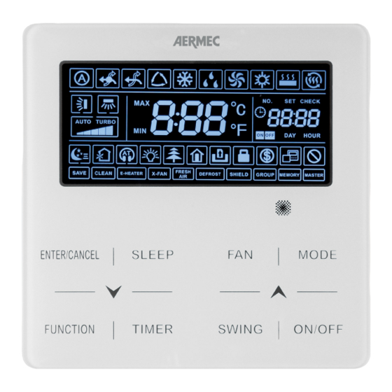
Wired panel - MVA unit The wired panel of the MVA unit allows display and rapid setting of the Wired panel - MVA unit machine's operating parameters. The card stores all the default set- tings and any modifications. After the absence of voltage for any period of time, the unit is able to start up again automatically, maintaining the original settings. - Page 5 The following table indicates which functions match the various icons available on the wired panel's LCD display: Function available Alarm Function on models Function not available Function not available Function not available Indicates that AUTOMATIC mode is active (only available on the MASTER unit) All models Indicates that COOLING mode is active (only available if the MASTER unit is set with a All models...
- Page 6 Function not available Indicates that the key lock function is active on the panel Indicates that energy saving mode is active on the indoor unit connected Indicates that the wired panel is a slave (i.e. two wired panels are connected to the indoor unit: one master and one slave) Indicates that an attempt has been made to use a locked panel using monitoring soft- ware (MVA MONITORING)
-
Page 7: User Interface (Buttons)
User interface (buttons) Alarm Function Selects or Cancels desired function Sets night-time comfort mode Activates or de-activates certain extra functions Sets data for unit timers This button is used to decrease the selected data or pass to the previous data Sets fan speed: Sets the operating mode for the unit: Sets automatic delivery fin oscillation (on units where this is envisaged) -
Page 8: Dimensions Of The Wired Panel
Installing the wired panel WARNING: MVA SYSTEMS MUST HAVE A MASTER ONLY ONE) FOR CORRECT MANAGEMENT OF THE OPERATING MODES. FOR THE SETTING PROCEDURE, REFER TO THE SPECIFIC SECTION. Dimensions of the wired panel: [mm] 35,5 42,5 Serial connection: The wired panel communicates with the Indoor unit through a serial port; it is possible to select several Indoor unit management configurations using the wired panel: SINGLE connection, where the unit (or group of units) DUAL connection, where the unit (or group of units) -
Page 9: Examples Of Serial Connection Between Wired Panel And Indoor Unit
Examples of serial connection between wired panel and indoor unit: The first serial connection possibility envisages a panel (re- previous page) for each unit; this solution allows customised minder: each individual unit of group of units can be man- settings for the timer, setpoint and ventilation speed for each aged by a single panel or by two panels connected to the Indoor unit;... - Page 10 Wired panel installation procedure: The first operation needed to install the wired After opening the wired panel, separate the front part from the rear body. panel is to open it using a flat screwdriver by pressing in the specific slot on the base of the panel.
- Page 11 After connecting the serial cable, close the panel again by aligning the upper and lower bodies and pressing until the upper body hooks up with the lower body. Notes for installing the wired panel It is advised not to install the wired panel where it may come into contact with water or direct sunlight;...
-
Page 12: Functions Available From Wired Panel
Functions available from wired panel Switching the indoor unit ON and OFF: The Indoor unit (or group of indoor units) managed by the wired panel is/are turned on and off using the ON/Off button; every time it is pressed thereafter will switch the connect Indoor unit ON or OFF. Indoor unit ON Indoor unit OFF... -
Page 13: Modifying The Operating Mode For The Indoor Unit
Modifying the operating mode for the indoor unit: The operating mode of the Indoor unit (or group of indoor units) managed by the wired panel can be modified using the MODE button; every time it is pressed thereafter will switch between one mode and the next (following the sequence indicated below); available modes are: Auto ( ): This function automatically selects the most suitable operating mode based on the indoor temperature;... -
Page 14: Modifying The Operating Temperature
Modifying the operating temperature: To modify the operating temperature, regardless of the operating mode (except for Ventilation Only which does not use the operating setting), simply press the buttons ( ) or ( ) respectively to decrease or increase the operating setting by 1°C; Operating temperature Modifying fan speed: The Ventilation speed (in all operating modes except for dehumidification) of the Indoor unit (or group of indoor units) managed... -
Page 15: Modifying The Programmed On/Off Timer (Countdown Mode)
WARNING: the system envisages two types of timer management: • COUNTDOWN mode this mode manages programmed unit on-off operations by specifying an “interval” (in hours) after which the unit will switch on or off; • CLOCK mode: this mode manages programmed unit on-off operations by specifying a time when the operations will be per- formed (in this case, the system clock is activated and displayed);... -
Page 16: Set System Time (Only Used In Clock Mode)
Set system time (only used in CLOCK mode): To set the time on the system clock (only used if CLOCK mode is selected in the operating parameters, parameter P33), perform the following operations: Press and hold down the “TIMER” button (5 seconds); at this stage, the symbol ( ) appears will flash to indicate that system time modification mode has been selected;... -
Page 17: Modifying The Programmed On/Off Timer (Clock Mode)
Modifying the programmed ON/OFF timer (CLOCK mode): Clock mode is used to manage several functions: (a) time band management: this function is used to set a switch ON time and a subsequent switch OFF times, thereby defin- ing a time band within which the Indoor unit will operate; (b) only programmed switch ON: this function is used to set a switch ON time for the unit;... - Page 18 WARNING: once the unit is switched ON using a timer function, it will resume the functions and settings in use before the system was switched off for the last time.
-
Page 19: Set Delivery Fin Swing
Set delivery fin SWING: To set delivery fin swing (function NOT AVAILABLE on canalised models), simply press the “SWING” button; every time it is pressed thereafter will switch between one function status to another (following the sequence indicated below); SWING mode icon Continuous SWING mode SWING dis-enabled SWING locked mode... -
Page 20: Set Quiet Function (Reduces The Noise Generated By The Indoor Unit)
Set QUIET function (reduces the noise generated by the indoor unit): The system envisages two different types of operation: “QUIET” and “AUTO QUIET”, which differ in terms of the logic they use to manage fan speed. To set this function, perform the following operations: Press the “FUNCTION”... -
Page 21: Set Night-Time Comfort Function
Set Night-Time Comfort function: To set the night-time comfort function (which is not available in AUTO mode of VENTILATION ONLY mode), simply press the “SLEEP” button while the unit is ON; this function will manage the unit in relation to a curve ensuring the best comfort together with low noise level;... -
Page 22: Set The Display Function On The Indoor Unit (Led And Two-Figure Display)
Set the DISPLAY function on the indoor unit (led and two-figure display): To activate or de-activate illumination of the indoor unit display (obviously except for canalised units), perform the following operations: Press the “FUNCTION” key until the icon for this function appears ( );... -
Page 23: Set The Energy Saving Function (Active On Indoor Unit)
Set the ENERGY SAVING function (active on indoor unit): This mode is available for heat and cool operations (in the first instance a minimum set is defined, while in the latter case a maximum set is defined as the setpoint limits beyond which it will not be possible to operate the machine); to see this function (with the unit ON), perform the following operations: Press the “FUNCTION”... -
Page 24: Set Indoor Unit Filter Cleaning Alarm
Set indoor unit FILTER CLEANING alarm: This function is used to set a certain number of operating hours after which the unit will send a message requesting that the air filter be pulled out and cleaned (for the filter removal and cleaning procedure, refer to the indoor unit installation manual); to set this function (with the unit ON), perform the following operations: Press the “FUNCTION”... -
Page 25: Set The X-Fan Function On Indoor Unit
Set the X-FAN function on indoor unit: This function is used to dry the coil (only during cool and dehumidification modes) if the unit is switched off before reaching the desired setpoint, in order to avoid the formation of mould or bacteria on the coil; to activate or de-activate this function, perform the following operations: Press the “FUNCTION”... -
Page 26: Set The Antifreeze Function On Indoor Unit
Set the ANTIFREEZE function on indoor unit: This function (only in Heat mode) allows setting a minimum room temperature; after setting it, the function is activated automat- ically if the room temperature falls below 6°C and is then deactivated when the temperature rises above 10°C; to activate or de-activate this function, perform the following operations: Press the “FUNCTION”... -
Page 27: Set Key Lock On Wired Panel
Set key LOCK on wired panel: This function is used to lock the buttons of the wired panel connected to the unit; to activate or de-activate this function, perform the following operations: press buttons ( ) and ( ) simultaneously for at least 5 seconds. The icon ( ) then appears to indicate button lock activation;... -
Page 28: Display Indoor Unit Operating Parameters
Display indoor unit OPERATING PARAMETERS: This function is used to display a series of operating parameters (each code is associated with the letter “C”); the parameters in this menu may not be modified but only displayed (read only); to read the operating parameters, perform the following op- erations: press the “FUNCTION”... -
Page 29: List Of Operating Parameters (Read-Only Data)
(for more information as regards system monitoring software, refer to www.aermec.com) This parameter is used to scroll all the project numbers (and consequently all the units in the system) to search for any errors;... - Page 30 Number of units in the This parameter indicates (in the timer zone) the number of units in any group group connected to the wired panel Display external temper- This parameter indicates (in the timer zone) the temperature of the external air ature;...
-
Page 31: Activation Of Indoor Unit Operating Parameter Modification Menu
Activation of indoor unit OPERATING PARAMETER modification menu: WARNING: accidental modification of these parameters may cause malfunctions or block the entire system; reminder: setting or modifying these parameters must ONLY be performed by the technical assistance service or personnel having the necessary technical skills. - Page 32 This parameter performs a test on the group (if a group has been created) in order to specify how many indoor units belong to it. This test checks whether the number set in the parameter matches the number of units detected by the system in the group;...
- Page 33 This parameter is used to define a heat setpoint used in AUTO mode (reminder: the auto mode is only available on the master unit); to set the parameter, proceed as follows: (1) Select the operating parameter “P38”; Heat set for 20°C 16°C~29°C (2) Press the “MODE”...
-
Page 34: Display Operating Errors Or System Messages
Display operating errors or system messages: These units envisage signals for various alarms, operating errors or system messages using a code shown on the wired panel display (as well as on the indoor unit display for units where this is envisaged); alarm codes and related causes are listed below. WARNING: reminder: in the event of an alarm, the unit must be switched off and the technical assistance service contacted for any kind of intervention on the unit. - Page 35 Type Code Description signal Outdoor unit Temperature sensor error on compressor discharge 3 Outdoor unit Temperature sensor error on compressor discharge 4 Outdoor unit Temperature sensor error on compressor discharge 5 Outdoor unit Temperature sensor error on compressor discharge 6 Outdoor unit Compressor power supply current sensor error 1 Outdoor unit...
- Page 36 Type Code Description signal Outdoor unit Under-cooling probe error (fluid leak) Outdoor unit Under-cooling probe error (gas leak) Outdoor unit Error on fluid separator inlet probe Outdoor unit Error on fluid separator outlet probe Outdoor unit Humidity probe error Outdoor unit Coil outlet probe error Outdoor unit Oil return temperature probe error...
- Page 37 Type Code Description signal Indoor unit Air quality alarm Indoor unit Incompatibility between indoor and outdoor units Indoor unit Indoor unit control electric card error Indoor unit Room air sensor error Indoor unit Error on temperature probe on coil inlet Indoor unit Error on temperature probe on coil outlet Indoor unit...
- Page 38 Type Code Description signal Debug codes Refrigerant low protection Debug codes Addressing error on compressor control card Debug codes Electronic expansion valve abnormal function alarm Debug codes Indoor unit refrigerant circuit malfunction Debug codes Outdoor unit refrigerant circuit malfunction Debug codes Master unit set successfully Debug codes Insufficient gas added...
- Page 40 Aermec S.p.A. se réserve le droit de modifier à tous estime necesarias para mejorar el producto. Im Sinne des technischen Fortsschrittes behält sich AERMEC S.p.A.
Need help?
Do you have a question about the WRC and is the answer not in the manual?
Questions and answers