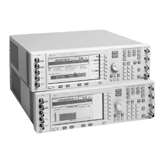
Agilent Technologies ESG Series Installation Note
Esg family signal generators. cpu/motherboard q501 relocated to chassis kit
Hide thumbs
Also See for ESG Series:
- User and programming manual (446 pages) ,
- Quick start manual (31 pages) ,
- Manual supplement (31 pages)
Summary of Contents for Agilent Technologies ESG Series
- Page 1 Installation Note Agilent Technologies ESG Family Signal Generators CPU/Motherboard Q501 Relocated to Chassis Kit Part Number E4400-60229 Part Number E4400-90379 Printed in USA September 2001...
- Page 2 The information contained in this document is subject to change without notice. Agilent Technologies makes no warranty of any kind with regard to this material, including but not limited to, the implied warranties of merchantability and fitness for a particular purpose. Agilent Technologies shall not be liable for errors contained herein or for incidental or consequential damages in connection with the furnishing, performance, or use of this material.
- Page 3 To Be Performed By: ... (X) Agilent Technologies Service Center ( ) Personnel Qualified by Agilent Technologies ( ) Agilent Technologies personnel on-site Estimated Installation Time: ...
-
Page 4: Installation Kit Parts List
Installation Kit Parts List Quantity Description Part Number Comments Q501 Assembly E4400-60221 Q501/Harness Q501 Plate with PEM E4400-00040 Nut Plate for chassis mount Q501 Plate without PEM E4400-00041 Plate located under Q501 Insulator bushing 0340-1162 Nylon washer insulates screw Screw 3MMX10 0515-0374 Screw attaches Q501 to chassis Connector Header 3 pin... - Page 5 Verifying the Functionality of the Signal Generator Power on the Signal Generator and Check for Error Messages This procedure verifies that the signal generator powers up and that the internal instrument check identifies no errors. The internal check evaluates the correctness of operation and returns an error message if a problem is detected.
- Page 6 Installation Procedure Save all hardware so it can be re-installed. Before you disassemble the instrument, turn the power switch off WARNING and unplug the instrument. Failure to unplug the instrument can result in personal injury. Electrostatic discharge (ESD) can damage or destroy electronic CAUTION components.
- Page 7 Figure 1 Installation Note E4400-90379...
- Page 8 Figure 2 Installation Note E4400-90379...
- Page 9 Figure 3 Installation Note E4400-90379...
- Page 10 Assemble Q501 to Front Inside of Chassis 1. Place Q501 nut plate with pem, part number E4400-00040, on the outside front of the chassis at slot 3 location. Place pem through slot 3. See Figure 2. Place plate without pem, part number E4400-00041, inside the front chassis over slot 3 while holding Q501 nut plate in position.
- Page 11 Figure 4 Figure 5 Installation Note E4400-90379...
- Page 12 Re-Assemble the Instrument 1. Turn the instrument off and unplug it. 2. Reinstall the instrument top cover with the 11 screws that secure it. Torque all T-10 Torque screws to 9 in-lbs. Refer to Figure 3. Reinstall the instrument’s external covers by reversing the removal procedure. a.


