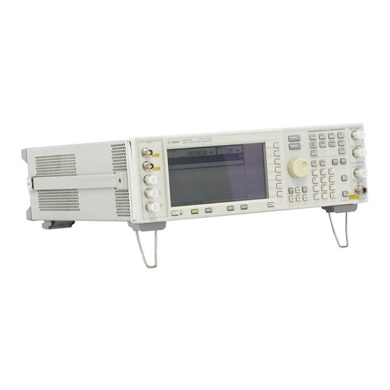
Agilent Technologies ESG-D Series Installation Notes
Signal generators data generator assembly replacement kit option un3/un4 to un8 + un9
Hide thumbs
Also See for ESG-D Series:
- Service manual (271 pages) ,
- Manual supplement (117 pages) ,
- Installation notes (20 pages)
Advertisement
Quick Links
Installation Note
Agilent Technologies ESG-D Series Signal Generators
Data Generator Assembly Replacement Kit
(Option UN3/UN4 to UN8 + UN9)
Kit Part Number E4400-60767
Models: E4430B, E4431B, E4432B, and E4433B
Part Number E4400-90663
Printed in USA June 2008
Supersedes None
Advertisement

Summary of Contents for Agilent Technologies ESG-D Series
- Page 1 Installation Note Agilent Technologies ESG-D Series Signal Generators Data Generator Assembly Replacement Kit (Option UN3/UN4 to UN8 + UN9) Kit Part Number E4400-60767 Models: E4430B, E4431B, E4432B, and E4433B Part Number E4400-90663 Printed in USA June 2008 Supersedes None...
- Page 2 The information contained in this document is subject to change without notice. Agilent Technologies makes no warranty of any kind with regard to this material, including but not limited to, the implied warranties of merchantability and fitness for a particular purpose. Agilent Technologies shall not be liable for errors contained herein or for incidental or consequential damages in connection with the furnishing, performance, or use of this material.
- Page 3 Option UN3/UN4 to UN8 + UN9 Product Affected: ......E4430B, E4431B, E4432B, E4433B ESG-D Series Signal Generators Serial Numbers: .
-
Page 4: Installation Kit Parts List
Installation Kit Parts List Item Quantity Description Part Number Opts Board Assembly, Real-time I/Q Baseband Generator (A7) E4400-60070 Board Assembly, Generator/8 Meg (A8) E4400-60195 Option UN9 Label 7120-1232 Ribbon Cable Interconnect (W19) 8120-8349 Ribbon Cable (W18) 8120-8457 SMB Cable (W25/W26) 8120-8748 Coax Cable (W3/W4/W5) Longer cables, if needed 8120-5063... - Page 5 Verifying the Functionality of the Signal Generator Power On the Signal Generator and Check for Error Messages This procedure verifies that the signal generator powers up and that the internal instrument check identifies no errors. 1. Turn power on to the signal generator by pressing the power switch. The green LED will light. Let the signal generator warm up for one hour.
- Page 6 Removing Option UN3 or UN4 Use the following procedure to remove Option UN3 or UN4 as a firmware selection and to remove the hardware associated with Option UN3/UN4. Removing Option UN3/UN4 in Firmware 1. Preset the signal generator 2. In the MENUS key group, press the hardkey Utility 3.
- Page 7 Figure 1 Cover Removal Figure 2 Option UN3/UN4 A7 Baseband Generator Board and Cables...
- Page 8 Figure 3 Option UND A5 Dual Arb Board and Cables Figure 4 Option UN7 A6 Bit Error Rate Test Board and Cables...
- Page 9 Figure 5 Option UN3/UN4 A8 Data Generation Board and Cables...
- Page 10 Installing Option UN8 + UN9 Hardware and Cables Refer to Figure 6 Figure 7 on page 12 to assist you in installing the new A7 and A8 assemblies. NOTE If the signal generator has Option UND installed, you will also need to refer to Figure 3 on page 1.
- Page 11 d. A18W1 ribbon cable from the A18 board to A6P4 11. Connect the W27 ribbon cable between A7P10 and A8P4. 12. Connect the W19 ribbon cable between A7P300 and A8P3. 13. Remove the W25 (INT Q) cable between the motherboard connector A14P103 and the A15 daughterboard and replace it with the W25 cable provided in this upgrade kit (Figure 7 on page 12).
- Page 12 Figure 6 Option UN8/UN9 Top View Figure 7 Cables W25 and W26...
- Page 13 Verifying Cable Connections Verify that all cables listed in the following table are installed and routed as shown in Figure Figure Figure 6 Figure Cable Routing (Front to Rear) Cable Description Reference Color Connection Point to Point Designator Number Option UN8/UN9 Only (Figure 6 on page Ribbon Cable Interconnect A7P300 to A8P3...
- Page 14 Figure 8 Options UN9/UN7/UND Top View...
-
Page 15: Installing New Firmware
Installing New Firmware If required, upgrade the instrument to the latest ESG-B firmware. Verifying the New Firmware To verify the new firmware has been downloaded into the signal generator, press > Utility > . The new firmware revision and firmware date should be Instrument Info/Help Mode Diagnostic Info displayed under “Instrument Information”. - Page 16 Reassembling the Signal Generator Refer to Figure 1 on page 1. Turn off the line power switch on the signal generator and disconnect the line cord. 2. Replace the top cover and torque the 11 screws that secure it to 9 in-lb. 3.


