Agilent Technologies ESG Series Installation Manual
Hide thumbs
Also See for ESG Series:
- User and programming manual (446 pages) ,
- Quick start manual (31 pages) ,
- Manual supplement (31 pages)
Table of Contents

Related Manuals for Agilent Technologies ESG Series


Summary of Contents for Agilent Technologies ESG Series
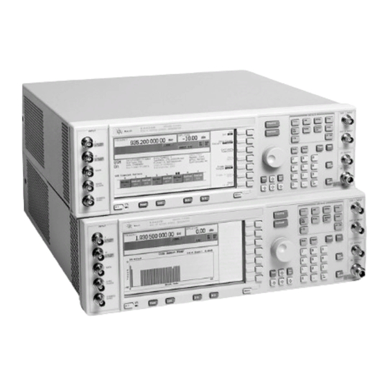
- Page 1 Installation Note Agilent Technologies ESG Series Signal Generators (A Models) CPU/Motherboard (Q501 relocated to Chassis) Replacement Kit: Part Number E4400-60238 Part Number E4400-90388 Printed in USA September 2000 Supersedes: July 2000...
- Page 2 The information contained in this document is subject to change without notice. Agilent Technologies makes no warranty of any kind with regard to this material, including but not limited to, the implied warranties of merchantability and fitness for a particular purpose. Agilent Technologies shall not be liable for errors contained herein or for incidental or consequential damages in connection with the furnishing, performance, or use of this material.
-
Page 3: Installation Kit Parts List
ESG Series Signal Generators: Part Number E4400-60238 Product Affected:......Agilent E4400A, E4420A, E4421A, E4422A, E4430A, E4431A, E4432A and E4433A Series Signal Generators. -
Page 4: Tools Required
Tools Required Ratchet 21 in-lb Hand Torque Driver 9 in-lb Hand Torque Driver 6 in-lb Torxdriver T-10 Torxdriver T-15 5/8 Socket 3/16 Socket 9/32 Socket Safety Considerations WARNING Before you disassemble the instrument, turn the power switch off and disconnect the line cord. Failure to unplug the Signal Generator can result in personal injury. - Page 5 Check Instrument Functionality The functionality check verifies that the signal generator powers up and that the internal instrument check identifies no errors. The internal check returns an error message if a problem is detected. 1. Turn on power to the signal generator. Let the instrument warm up for at least five minutes. 2.
- Page 6 Remove the Signal Generator Covers 1. Turn the signal generator’s power switch off and disconnect the line cord. 2. Refer to Figure 1. Remove the two strap handles (item 1) from each side of the signal generator by loosening the two handle screws (item 2). 3.
- Page 7 6. Refer to Figure 2. Remove the top chassis cover (item 2) by removing the 11 screws (item 1) that secure it. Figure 2 Top Chassis Cover Removal Installation Note E4400-90388...
- Page 8 7. Refer to Figure 3. Turn the signal generator over and remove the bottom chassis cover (item 3) by removing the 15 bottom chassis cover screws (item 2). Figure 3 Bottom Chassis Cover Removal Installation Note E4400-90388...
-
Page 9: Removing The Rear Panel
Removing the Rear Panel 1. Refer to Figure 4. Remove the nuts and washers securing the five BNC connectors (item 1) at the base of the rear panel. 2. Remove the hex screws and washers that secure the AUXILIARY INTERFACE (item 2) and GPIB connectors (item 3) to the rear panel. - Page 10 Remove the PC Boards and Cables 1. Refer to Figure 5. If the signal generator has Option 1EH, remove the Baseband Generator board (A7). 2. If the signal generator has Option UN3/4, remove the Baseband Generator board (A7) and the Pattern Ram board (A8).
- Page 11 Removing Transistor Q501 and the CPU/Motherboard 1. Refer to Figure 6. The transistor, Q501, is located on the CPU/Motherboard (A14). Remove the screw (item 1) securing the CPU/Motherboard to the signal generator chassis. 2. Remove the Q501 transistor screw (item 2). An insulated bushing is between the CPU/Motherboard and the signal generator chassis.
- Page 12 Installing the New CPU/Motherboard When installing the new motherboard, remember to insert the tab and daughterboard NOTE connector into the corresponding slots of the signal generator chassis before securing it with the screws. 1. Refer to Figure 7. Secure the new CPU/Motherboard onto the signal generator chassis by installing a screw into the hole adjacent to item 2.
- Page 13 Installing Q501 on the Signal Generator Chassis NOTE Q501 is attached to the harness. 1. Refer to Figure 8. Place the plate (with pem nut) through the top opening in slot 3. 2. Hold Q501, the inner plate and the outer plate (with pem nut) and place the bushing against Q501. 3.
- Page 14 Connect Q501 to CPU/Motherboard 1. Refer to Figure 9. Connect the Q501 assembly wiring harness connector to the CPU/Motherboard (A14). 2. Insure that the harness is properly seated. Figure 9 Q501 Wiring Harness to CPU/Motherboard Installation Note E4400-90388...
-
Page 15: Reassemble The Signal Generator
Reassemble the Signal Generator 1. Reconnect all cables to the CPU/Motherboard. Refer to the service guide if necessary. Verify that all cables are correctly reconnected. 2. Reinstall the rear panel to the signal generator. Reverse the rear panel procedure to attach the rear panel. - Page 16 Installation Note E4400-90388...