Agilent Technologies ESG series Quick Start Manual
Signal generators
Hide thumbs
Also See for ESG series:
- User and programming manual (446 pages) ,
- Manual supplement (31 pages) ,
- Installation manual (16 pages)

Related Manuals for Agilent Technologies ESG series


Summary of Contents for Agilent Technologies ESG series
-
Page 1: Quick Start Guide
Quick Start Guide Agilent Technologies ESG Family Signal Generators Serial Number Prefixes: (Affix Label Here) Part No. E4400-90326 Printed in USA October 2000 Supersedes April 2000 © Copyright 1999, 2000 Agilent Technologies... -
Page 2: Table Of Contents
Contents 1. Getting Started The Signal Generator at a Glance ........1-2 Creating an FM Signal . -
Page 3: Getting Started
ESG Family Signal Generators Getting Started This chapter will help you learn how to do the following with your signal generator: • create an FM signal • generate step and list sweeps • use the save and recall functions • set up a digital modulation in GSM format (Option UN8 only) Quick Start Guide... -
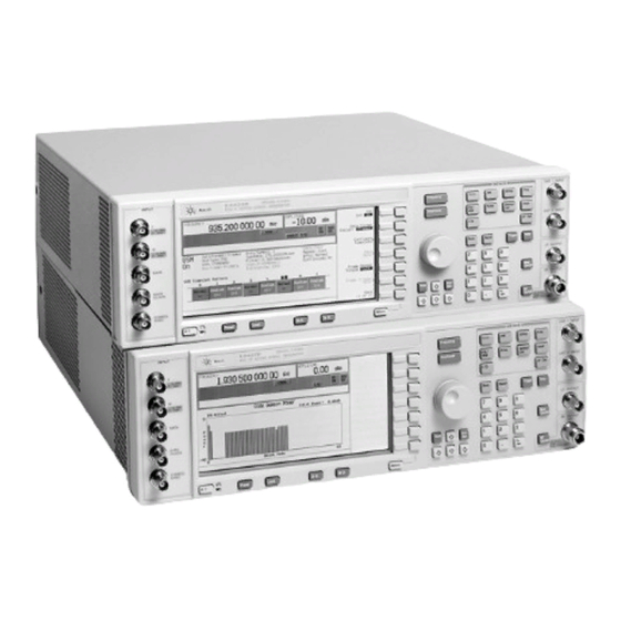
Page 4: The Signal Generator At A Glance
Getting Started ESG Family Signal Generators The Signal Generator at a Glance The Signal Generator at a Glance Refer to the figure and descriptions below as you use the procedures in this chapter. For detailed front and rear panel information, refer to Chapter 2, “Exploring the User Interface.”... -
Page 5: Creating An Fm Signal
ESG Family Signal Generators Getting Started Creating an FM Signal Creating an FM Signal This procedure will show you how to configure the signal generator to output a frequency-modulated signal with the following characteristics: • carrier frequency set to 104.9 MHz •... -
Page 6: Setting The Fm Deviation
Getting Started ESG Family Signal Generators Creating an FM Signal Setting the FM Deviation φ Press The first level menu of FM softkeys is displayed. Press the softkey. FM deviation becomes the active function and the preset value FM Dev for FM deviation is displayed in the active entry area. -
Page 7: Creating A Step Sweep And A List Sweep
ESG Family Signal Generators Getting Started Creating a Step Sweep and a List Sweep Creating a Step Sweep and a List Sweep This section will show you two ways to set up the signal generator to sweep a defined set of points. -
Page 8: Turning On Continuous Step Sweep
Getting Started ESG Family Signal Generators Creating a Step Sweep and a List Sweep Press the softkey. This sets the new power level for the end of the step sweep to Ampl Stop Enter using the numeric 0 dBm. keypad and press the softkey. -
Page 9: Configuring A List Sweep Using Step Sweep Data
ESG Family Signal Generators Getting Started Creating a Step Sweep and a List Sweep Configuring a List Sweep Using Step Sweep Data Press the This toggles the softkey from Sweep Type List Step Sweep Type List Step Step softkey. List Press the Another menu is displayed with softkeys that you will use to Configure List Sweep... -
Page 10: Turning On List Sweep For A Single Sweep
Getting Started ESG Family Signal Generators Creating a Step Sweep and a List Sweep Turning On List Sweep for a Single Sweep Press This moves the softkey menu up one level. Notice that the Return softkey is still set to sweep both frequency and amplitude Sweep data. -
Page 11: Saving And Recalling An Instrument State
ESG Family Signal Generators Getting Started Saving and Recalling an Instrument State Saving and Recalling an Instrument State Using this procedure, you will learn how to save instrument settings to a memory register and to recall the settings. Creating an Instrument State Press This sets the signal generator to its factory-defined instrument Preset... -
Page 12: Saving An Instrument State
Getting Started ESG Family Signal Generators Saving and Recalling an Instrument State Saving an Instrument State Press followed by the The sequence number becomes the active function. The signal Save softkey. generator displays the last sequence that you have used. Select Seq Enter using the numeric... -
Page 13: Setting Up A Digital Modulation In The Gsm Format
ESG Family Signal Generators Getting Started Setting Up a Digital Modulation in the GSM Format Setting Up a Digital Modulation in the GSM Format You must have an ESG-D or ESG-DP Series Signal Generator with Option UN8 NOTE to perform this procedure. Using this procedure you will set up the signal generator to output a GMSK digitally modulated signal in the GSM format with the following characteristics: •... -
Page 14: Selecting The Data Format
Getting Started ESG Family Signal Generators Setting Up a Digital Modulation in the GSM Format Selecting the Data Format Press . Then press the This selects the GSM communications standard. Mode following softkeys: (if it Real Time I/Q Baseband appears) > >... -
Page 15: Setting Up Timeslot 7
ESG Family Signal Generators Getting Started Setting Up a Digital Modulation in the GSM Format Press the softkey. This changes the transmitted data to a fixed 4-bit repeating FIX4 sequence. The default 4-bit repeating sequence of 0000 is shown in the active entry area of the display. Enter using the numeric This changes the pattern from 0000 to 1010. -
Page 16: Turning On The Gsm Format And The Modulation
Getting Started ESG Family Signal Generators Setting Up a Digital Modulation in the GSM Format Turning On the GSM Format and the Modulation The signal generator is now configured to burst two uplink timeslots with a −5.0 dBm, GMSK digitally modulated carrier at 891 MHz. Follow these remaining steps to output the framed data. -
Page 17: Exploring The User Interface
ESG Family Signal Generators Exploring the User Interface This chapter provides you with an overview of your signal generator’s user interfaces: • front panel hardkeys and connectors • display fields and annotations • rear panel connectors Quick Start Guide... -
Page 18: Front Panel
Exploring the User Interface ESG Family Signal Generators Front Panel Front Panel The following pages describe the numbered items shown in the figure below. Quick Start Guide... - Page 19 ESG Family Signal Generators Exploring the User Interface Front Panel This female BNC input connector accepts a 1-V signal for FM, EXT 1 INPUT ΦM, and AM. This female BNC input connector accepts a 1-V signal for FM, EXT 2 INPUT ΦM, AM, and pulse modulation.
- Page 20 Exploring the User Interface ESG Family Signal Generators Front Panel key cancels the current active function and moves you 11. Return Return from your current softkey menu to the softkey menu that precedes Press this key and hold it down to cause the display background to 12.
- Page 21 ESG Family Signal Generators Exploring the User Interface Front Panel The LCD display provides information on the current instrument 21. Display state such as modulation status, frequency and amplitude settings, status indicators, and error messages. Softkey labels corresponding to their adjacent keys are located on the right-hand side of the display.
- Page 22 Exploring the User Interface ESG Family Signal Generators Front Panel This hardkey lets you restore any instrument state that you 30. Recall previously saved in a memory register. You can save up to 100 different instrument states in a combination of 100 memory registers and 10 register sequences.
-
Page 23: Display
ESG Family Signal Generators Exploring the User Interface Display Display The following pages describe the numbered items shown in the figure below. The current CW frequency setting is shown in this portion of the Frequency display. Area The current output power level setting is shown in this portion of Amplitude Area the display. - Page 24 Exploring the User Interface ESG Family Signal Generators Display Abbreviated error messages are reported in this space. When Error Messages multiple error messages occur, only the most recent message Area remains displayed. All of the reported error messages with details can be viewed by pressing >...
- Page 25 ESG Family Signal Generators Exploring the User Interface Display This annunciator appears if the burst envelope modulation is ENVLP turned on. This annunciator is present only on ESG-D and ESG-DP Series Signal Generators. This annunciator appears when an error message is placed in the error queue.
- Page 26 Exploring the User Interface ESG Family Signal Generators Display This annunciator toggles between RF OFF and RF ON and is RF OFF always visible in the display. This annunciator indicates whether the RF signal is present at the RF OUTPUT connector. The S annunciator appears when the signal generator has generated a service request (SRQ) over the GPIB.
-
Page 27: Rear Panel
ESG Family Signal Generators Exploring the User Interface Rear Panel Rear Panel The following pages describe the numbered items shown in the figure below. The power cord receptacle accepts a three-pronged cable that is AC Power shipped with the instrument. The line voltage is connected here. Receptacle The GPIB connector allows communications with compatible GPIB... - Page 28 Exploring the User Interface ESG Family Signal Generators Rear Panel This male DB-9 connector is an RS-232 serial port that can be used AUXILIARY for controlling the signal generator remotely. It is functionally INTERFACE equivalent to the GPIB connector. The TTL/CMOS-compatible DATA CLK OUT connector outputs a DATA CLK OUT clock signal for digital modulation data.
- Page 29 ESG Family Signal Generators Exploring the User Interface Rear Panel This input can accept either a TTL/CMOS low to TTL/CMOS high or 12. PATTERN TTL/CMOS high to TTL/CMOS low edge trigger. With Option UN8 TRIG IN this input triggers the internal digital modulation pattern generator to start a single pattern output or to stop and re-synchronize a pattern that is being continuously output.
- Page 30 Exploring the User Interface ESG Family Signal Generators Rear Panel With Option UN8 enabled, the BASEBAND GEN REF IN connector 18. BASEBAND accepts a 0 to +20 dBm sinewave or TTL squarewave signal from an GEN REF IN external 13-MHz timebase reference. This female BNC connector is present only on instruments with Options UND or UN8.
- Page 31 ESG Family Signal Generators Exploring the User Interface Rear Panel Use this connector to input the data streams for the bit-error-rate 26. BER DATA IN measurements. This female BNC connector is present only on instruments with Option UN7. Use this connector to input the clock signal for the bit-error-rate 27.