Agilent Technologies ESG-D Series Installation Notes
Signal generators option und upgrade kit
Hide thumbs
Also See for ESG-D Series:
- Service manual (271 pages) ,
- Manual supplement (117 pages) ,
- Installation notes (16 pages)
Advertisement
Quick Links
Installation Note
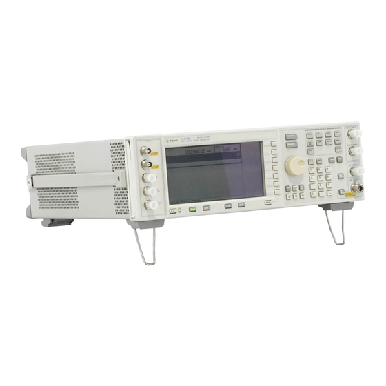
Agilent Technologies ESG-D and ESG-DP Series
Signal Generators Option UND Upgrade
Kit Part Numbers E4400-60166 and E4400-60181
Models: E4430B, E4431B, E4432B, E4433B, E4434B,
E4435B, E4436B and E4437B
Part Number E4400-90214
Printed in USA October 2004
Supersedes July 2000
Advertisement

Related Manuals for Agilent Technologies ESG-D Series


Summary of Contents for Agilent Technologies ESG-D Series
- Page 1 Installation Note Agilent Technologies ESG-D and ESG-DP Series Signal Generators Option UND Upgrade Kit Part Numbers E4400-60166 and E4400-60181 Models: E4430B, E4431B, E4432B, E4433B, E4434B, E4435B, E4436B and E4437B Part Number E4400-90214 Printed in USA October 2004 Supersedes July 2000...
- Page 2 The information contained in this document is subject to change without notice. Agilent Technologies makes no warranty of any kind with regard to this material, including but not limited to, the implied warranties of merchantability and fitness for a particular purpose. Agilent Technologies shall not be liable for errors contained herein or for incidental or consequential damages in connection with the furnishing, performance, or use of this material.
- Page 3 To Be Performed By: ..... . (X) Agilent Service Center (X) Personnel Qualified by Agilent Technologies (X) Customer Estimated Installation Time: ....
- Page 4 Upgrade Kit E4400-60166 (For Signal Generators without Options UN3/4 or UN8/9) The tools and kit contents required to install the Option UND upgrade for signal generators not equipped with Options UN3/4 or UN8/9 are described below. Tools Required T-10 TORX screwdriver T-15 TORX screwdriver Break away torque wrench, 9 in-lbs Ratchet, 21 in-lbs...
- Page 5 Upgrade Kit E4400-60166 Contents Quantity Part Item Description Std (No Number Opt’s This installation note E4400-90214 Dual arbitrary waveform generator board E4400-60187 Rear-panel interface board E4400-60145 Rear panel (Option UND) E4400-00031 W3, DATA to motherboard or 8120-5063 DATA to Data Generator (A8J2) (Option UN3/4 or UN8/9) W4, DATA CLOCK to motherboard or 8120-5063 DATA CLOCK to Data Generator (A8J1) (Option UN3/4 or UN8/9)
- Page 6 Upgrade Kit E4400-60181 (For Signal Generators Equipped with Options UN3/4 or UN8/9) The tools and kit contents required to install the Option UND upgrade for signal generators equipped with Options UN3/4 or UN8/9 are described below. Tools Required T-10 TORX screwdriver T-15 TORX screwdriver Scissors WARNING...
-
Page 7: Functionality Check
Functionality Check This procedure verifies that the signal generator powers up and that the internal instrument check does not identify any errors. The internal check returns an error message if a problem is detected. 1. Turn the signal generator’s power switch on. The green LED will light. Let the signal generator warm up for 5 minutes. - Page 8 Installation Procedure Remove the signal generator covers 1. Turn the signal generator’s power switch off and disconnect the line cord. 2. Refer to Figure 1 on page 8. Remove the four bottom feet (item 3). 3. Remove the two strap handles (item 1) from each side of the signal generator by loosening the two screws (item 2) on each handle.
- Page 9 Figure 2 Top Chassis Cover Removal Remove the Standard Signal Generator Rear Panel 1. Refer to Figure 3 on page 10. Remove the 15 screws (item 2) that secure the bottom chassis cover (item 3) and lift the chassis cover off. 2.
- Page 10 Figure 3 Bottom Chassis Cover Removal 3. Refer to Figure 4 on page 11. Remove the nuts and washers that secure the five BNC connectors (item 2). 4. Remove the hex screws and washers that secure the AUXILIARY INTERFACE (item 3) and GPIB (item 4) connectors to the rear panel.
- Page 11 Figure 4 Removing the Rear Panel and Rear Panel Parts Installation Note E4400-90214...
- Page 12 Removing Rear Panel Parts 1. Refer to Figure 4 on page 11. Remove the nut (not shown) that attaches the green ground wire (A16W2) to the rear panel and remove the screws securing the line module (item 6). 2. Remove the chain screw securing the COHERANT CARRIER dust cap (item 7). 3.
- Page 13 Figure 5 Rear panel assembly Install the Option UND Rear Panel 1. Refer to Figure 4 on page 11. Attach the new Option UND rear panel to the signal generator chassis with the 10 screws (item 5). Torque to 9 in-lbs. 2.
- Page 14 Modify the Front Panel CAUTION Follow all precautions and directions for the safety solvent cleaner. 1. Refer to Figure 6 on page 15. Remove the nut and washer that secure the front panel I INPUT connector to W1. 2. Remove the nut and washer that secure the front panel Q input connector to W2. 3.
- Page 15 Figure 6 Front Panel Installation Note E4400-90214...
- Page 16 Install Option UND Board Assembly (Options UN3/4 or UN8/9 Not Installed) 1. Cut out a single Option UND label and attach it to the serial tag option location on the rear panel. This identifies the signal generator as having Option UND installed. 2.
- Page 17 Figure 7 Cable Locations (Option UN3/4 or UN8/9 Not Installed) Install the Option UND Board Assembly (Options UN3/4 or UN8/9 Installed) 1. Cut out a single Option UND label and attach it to the serial tag option location on the rear panel. This identifies the signal generator as having Option UND installed.
- Page 18 Figure 8 Cable Locations (Options UN8/9 Installed) Figure 9 Cables W25 and W26 Installation Note E4400-90214...
- Page 19 Cable Routing (front to rear) Color Reference Connection Cable Description Designator Point to Point Number Option UN8 Only (Figure 8 on page 18) RIBBON CABLE – A7P300 to A8P3 INTERCONNECT RIBBON CABLE – A7P10 to A8P4 INTERCONNECT BASEBAND GEN REF IN Rear Panel to A7P403 Q OUT Rear Panel to A7P404...
- Page 20 Installing and Verifying the New Firmware 1. Install the new firmware by following the instructions in the firmware upgrade installation note. 2. Perform the verification procedure described in the firmware upgrade installation note. Activate Option UND 1. Connect the line cord to the signal generator and turn the signal generator line switch on. Let the signal generator warm up for at least 30 minutes.