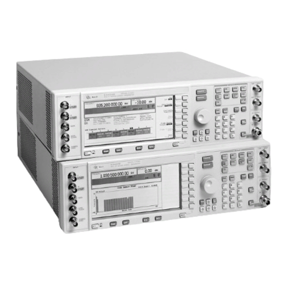
Agilent Technologies ESG Series Installation Note
Signal generators, semi-rigid cable replacement kits
Hide thumbs
Also See for ESG Series:
- User and programming manual (446 pages) ,
- Quick start manual (31 pages) ,
- Manual supplement (31 pages)
Advertisement
Quick Links
Advertisement

Summary of Contents for Agilent Technologies ESG Series
- Page 1 Installation Note Agilent Technologies ESG and ESG-D Series Signal Generators Semi-Rigid Cable Replacement Kits Kit Numbers E4400-60059, E4400-60060, E4400-60061, E4400-60176, E4400-60177, and E4400-60726 Part Number E4400-90096 Printed in USA August 2003 Supersedes: May 1998...
- Page 2 The information contained in this document is subject to change without notice. Agilent Technologies makes no warranty of any kind with regard to this material, including but not limited to, the implied warranties of merchantability and fitness for a particular purpose. Agilent Technologies shall not be liable for errors contained herein or for incidental or consequential damages in connection with the furnishing, performance, or use of this material.
-
Page 3: Tools Required
To Be Performed By: ..... . (x) Agilent Service Center (x) Personnel Qualified by Agilent Technologies (x) Customer Estimated Installation Time: .... -
Page 4: Installation Kit Parts List
Installation Kit Parts List Table 1 Replacement Cable Kit for W11 E4400-60059 Contents Item Quantity Description Part Number CBL AY-Synth Out E4400-20020 Retainer Cable E4400-40002 Retainer Ring 0410-1643 Installation Note E4400-90096 Table 2 Replacement Cable Kit for W12 E4400-60060 Contents Item Quantity Description... - Page 5 Tables 4 and 5 below describe the cable replacement kits for instruments equipped with Option UNB. Table 4 Replacement Cable Kit for W12 E4400-60176 Contents Item Quantity Description Part Number CBL RF Aux Out E4400-20130 Retainer Cable E4400-40002 Retainer Ring 0410-1643 Installation Note E4400-90096...
-
Page 6: Functionality Check
Functionality Check This procedure verifies that the signal generator powers up and that the internal instrument check identifies no errors. The internal check evaluates the correctness of operation and returns an error message if a problem is detected. 1. Turn power on to the signal generator by pressing the power switch. The green LED will light. Let the instrument warm up for one hour. - Page 7 Procedure Remove Instrument Cover 1. Remove the two strap handles (item 1) from each side of the signal generator by loosening the two screws (item 2) on each handle. 2. Remove the four bottom feet (item 3). 3. Remove the four rear feet (item 4) from the signal generator by removing the four screws (item 5) that secure them.
- Page 8 Remove A9, A11, and A12 Daughterboard Card Cage Boards Use this procedure to remove each of the following assemblies: • Output Board (A9) • Reference Board (A11) • Synthesizer/Doubler Board (A12) 1. Remove the right-side cover by removing the four screws that attach it to the instrument chassis. 2.
- Page 9 Replace W11, W12, and W14 Semi-Rigid Cables Remove Old Semi-Rigid Cables Refer to, Figure 4 for E4400 A-Series Signal Generators Figure 5 for E4400 B- and BU-Series Signal Generators or Figure 6 for E4400 B- and BU-Series Signal Generators with Option UNB 1.
- Page 10 Figure 5 W11, W12 and W14 Semi-Rigid Cable Locations for E4400 B- and BU-Series Signal Generators Installation Note E4400-90096...
- Page 11 Figure 6 W11, W12 and W14 Semi-Rigid Cable Locations for E4400 B- and BU-Series Signal Generators Option UNB Replace Semi-Rigid Cables 1. If you’re installing a new cable, refer to Figure 3. A new cable retainer (item 2) must first be attached to the end of the cable (item 4).
- Page 12 Press the front panel PRESET button to reset the signal generator. b. Rerun the “Functionality Check” on page 6 of this installation note. Perform the Following Adjustments and Performance Tests These adjustments are automated using the ESG Series Support Software NOTE Analog / Digital E4400-10001. Adjustments 1. Gain Adjust 2.


