Holzstar DB 900 Operating Instructions Manual
Wood lathe
Hide thumbs
Also See for DB 900:
- Instruction manual (16 pages) ,
- Instruction manual (8 pages) ,
- Operating instructions manual (8 pages)
Table of Contents
Advertisement
Advertisement
Table of Contents

Related Manuals for Holzstar DB 900


Summary of Contents for Holzstar DB 900
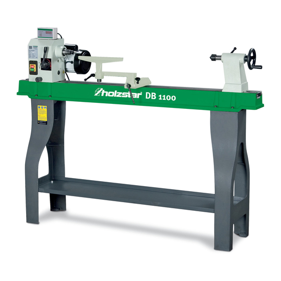
- Page 1 Operating instructions Wood Lathe DB 900 DB 1100 DB 1100 DB 900...
-
Page 2: Table Of Contents
13 Spare parts ..........17 13.1 Spare parts orders..........17 Copyright © 2020 Stürmer Maschinen GmbH, Hallstadt, 13.2 Spare parts drawing DB 900 ......18 Germany. 13.3 Spare parts drawing DB 1100 ......19 14 Electrical circuit diagram ......20 The contents of these operating instructions is the sole 15 EC-Declaration of Conformity .... -
Page 3: Introduction
Introduction Introduction 1.3 Disclaimer You have made a good choice by purchasing a HOLZ- All data in these operating instructions has been com- STAR Wood lathe DB-Series. piled on the basis of the state-of-the-art, valid standards and guidelines as well as our many years of expertise Carefully read the operating instructions prior to and experience. -
Page 4: Obligations Of The Operating Company
Safety - The operator must inform himself about the appli- cable occupational health and safety regulations WARNING! and determine additional hazards in a hazard as- This combination of symbol and signal term indicates sessment which are caused by the special working potentially hazardous situations which may cause conditions at the place of use of the machine. -
Page 5: Personal Protective Equipment
Safety Operator Safety boots The operator is instructed by the operating company about the assigned tasks and possible risks in case of The safety boots protect the feet against crushes, fall- improper behaviour. Any tasks which need to be perfor- ing parts and slipping over on slippery underground. -
Page 6: Safety Instructions
Safety 2.6 Safety instructions - Wear tight-fitting work clothing, safety glasses, safety shoes and hearing protection. Tie long hair to- gether. Do not wear watches, bracelets, chains, rings or gloves (rotating parts!) when working. NOTE! - Immediately eliminate any faults that impair safety. The instructions for use and maintenance must be - Never leave the machine unattended in operation read carefully before starting, using, servicing or... -
Page 7: Intended Use
- Never work on materials other than those specified for the intended use. - Only operate the lathe in a technically perfect condi- Model DB 900 tion. Max. turning Ø 306 mm - Never machine several workpieces at the same Max. -
Page 8: Type Plate
Transport, packaging, storage General risks during internal transport 4.1 Type plate WARNING: DANGER OF TIPPING The device may be lifted unsecured by a maximum of 2cm. Employees must be outside the danger zone, the reach of loads. Warn employees and, if necessary, advise employ- ees of the hazard. -
Page 9: Description Of The Device
19. Clamping, height adjustment of the tool rest 20. Locking bolt Fixed steady DB1100 5931030 21. Clamping lever for spindle head Fixed steady DB 900 5931050 External turning device DB1100 5931052 Carrier Set MK3. 3 pieces DB 900 and 5931056 DB 1100 DB-Series | Version 3.09... -
Page 10: Installation And Connection
It must be ensured that there is sufficient screws. freedom of movement for working. The installation site should meet the following criteria: 8.1 Model DB 900 - The surface must be level, firm and free of vibrati- 8.1.1Assembly of the machine frame ons. -
Page 11: Model Db 1100
Operation 8.1.3Mounting of spindle head 8.3 Electrical connection DANGER! Risk of death due to electric shock! Contact with live components may result in fatal injury. Switched-on electrical components can make uncontrolled movements and lead to serious injuries. Fig. 7: Mounting of spindle head ATTENTION! Fix the spindle clamping lever (Pos.1, Fig.7) of the DB 900 in the following order: clamping handle, compres-... -
Page 12: Speed Adjustment
Operation 9.2 Handling the clamping tools CAUTION! Danger of crushing! Improper work on the machine may result in injury to the upper limbs ATTENTION! Before starting up, check the electrical connection, Fig. 10: Handling the clamping tools cables and contacts. Mounting the face plate Use hearing protection! Screw the face plate hand-tight onto the main spindle. -
Page 13: Adjustment Of The Tailstock
Operation 9.5 Adjusting the tool rest Fig. 12: Adjustment of the spindle head Fig. 15: Adjusting the tool rest Step 1: Do not turn the spindle head counterclockwise Use the tool rest for safe guidance of the lathe tool and when it is in this position (Pos. -
Page 14: Care, Maintenance And Repair
Care, maintenance and repair 10 Care, maintenance and repair Choice of materials Defective wood tends to splinter and becomes a risk for DANGER! user and machine. Risk of death due to electric shock! Work pieces made of glued wood should only be proces- Contact with live components may result in fatal sed by an experienced craftsman. -
Page 15: Servicing
Troubleshooting 3. Occasionally unscrew the tailstock spindle, clean it Lubrication and spray it with dry lubricant. Grease the threaded spindle. NOTE! 4. Check the clamping of the tailstock and tool rest and readjust if necessary. During the maintenance of the lathe, all moving parts must be lubricated at least once a month. -
Page 16: Disposal, Reusing Used Machines
Disposal, reusing used machines Fault Possible cause Solution Strong vibrations. Workpiece deformed, un- Prepare the workpiece for turning by planing and sawing. round, has large weak points/ cracks or has not been prepa- red for turning. Spindle bearing is worn. Replace the spindle bearing. -
Page 17: Disposal Via Municipal Collection Points
Example The symbol on the product or its packaging indi- The handwheel for the Wood Lathe DB 900 must be or- cates that this product should not be treated as normal dered. The handwheel has the number 49 in the spare household waste, but must be returned to a collection parts drawing 1. -
Page 18: Spare Parts Drawing Db 900
The following spare parts drawings is intended to help identify the necessary spare parts. To order, please send a copy of the list of spare parts with the marked components to your dealer. Fig. 18: Spare parts drawing DB 900 DB-Series | Version 3.09... -
Page 19: Spare Parts Drawing Db 1100
Spare parts 13.3 Spare parts drawing DB 1100 Fig. 19: Spare parts drawing DB 1100 DB-Series | Version 3.09... -
Page 20: Electrical Circuit Diagram
Electrical circuit diagram 14 Electrical circuit diagram Fig. 20: Electrical circuit diagramEC Declaration of Conformity DB-Series | Version 3.09... -
Page 21: Ec-Declaration Of Conformity
According to Machinery Directive 2006/42/EC Annex II 1.A Manufacturer / distributor: Stürmer Maschinen GmbH Dr.-Robert-Pfleger-Straße 26 D-96103 Hallstadt hereby declares that the following product Product group: Holzstar® Woodworking machines Machine type: Wood Lathe Description of the machine*: DB 900 Item number *: 5920900... - Page 22 www.holzstar.de...
Need help?
Do you have a question about the DB 900 and is the answer not in the manual?
Questions and answers
Guten Tag, meine Drechselbank DB1100 - Moter benötigt sehr lange bis er die Drehzahl erreicht hat. Können Sie mir weiterhelfen. Danke
The Holzstar DB 900 lathe motor taking a long time to reach speed could be due to a defective switch or capacitor, or a problem with the electrical extension conductor. These issues should be checked by a qualified electrician.
This answer is automatically generated