Holzstar DB900 Instruction Manual
Hide thumbs
Also See for DB900:
- Operating instructions manual (22 pages) ,
- Instruction manual (8 pages) ,
- Operating instructions manual (8 pages)
Table of Contents
Advertisement
Quick Links
Advertisement
Table of Contents

Related Manuals for Holzstar DB900


Summary of Contents for Holzstar DB900
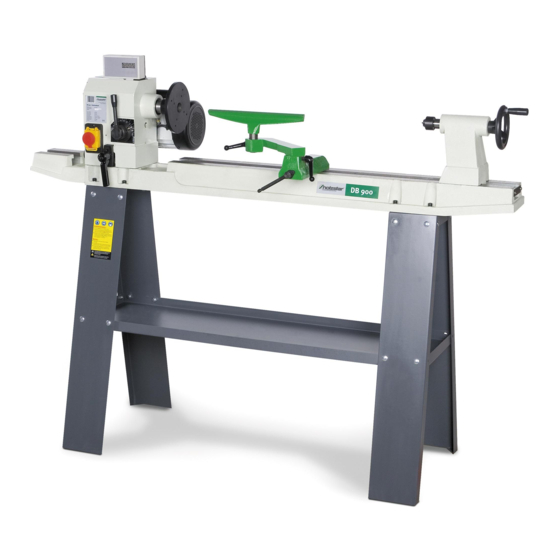
- Page 1 VARIABLE SPEED WOOD LATHE Model DB900 INSTRUCTION MANUAL...
-
Page 2: Table Of Contents
Assembly…………………………………………………………………….…………………………4-7 Adjustments………………………………………………………………………………………….….8-9 Operation………………………………………………………………….…………………………..10 Maintenance………………………………………………………………….…………………………10 Wiring diagram………………………………………………………………………………………..…11 Parts break-down…………………………………………………….……………………...………11-12 Parts list…………………………………………………………….………………….…………………13 TECHNICAL DATA Model number……………………… ……...………………………………………………… DB900 Motor…………………………………………….………………………… ………………………. 550W Speeds………………………………………………...…………………………..…… …500-2000RPM Distance between centers ………………………………….….…..…………………………..900mm Swing over bed……………………………………………….……………………………………305mm Drive spindle …………………………………………………………………….………………M33X3.5 Drive spindle through hold ………………………………….…………………………..…………10mm Tailstock spindle through hole………………………………..……………………………………10mm Tailstock spindle travel….…………………………………………………….……………………57mm... - Page 3 3. Guard against electric shock Avoid body contact with earthen or grounded surfaces. 4. Keep other persons away Do not let persons especially children not involved in the work touch the tools or the extension cord and keep them away from the work area. 5.
-
Page 4: Specific Safety Rules For Wood Lathe
Check for alignment of moving parts, binding of moving parts, breakage of parts, and any other conditions may affect its operation. A guard or other part that is damaged should be properly repaired or replaced by an authorized service center unless otherwise indicated in this instruction manual. Have defective switches replaced by an authorized service center. -
Page 5: Electrical Information
Electrical information Guidelines for using extension cords WARNING! THIS WOOD LATHE IS FOR INDOOR USE ONLY. DO NOT EXPOSE TO RAIN OR USE IN DAMP LOCATIONS. Make sure your extension cord is in good condition. When using an extension cord, be sure to use one heavy enough to carry the current your product will draw. -
Page 6: Assembly
WARNING! IF ANY PART IS MISSING OR DAMAGED, DO NOT PLUG THE WOOD LATHE IN UNTIL YOU HAVE REPLACED THE MISSING OR DAMAGED PART. For you satiety, complete the assembly of the lathe before plugging it into the power supply. 1. - Page 7 Installing the lathe on the leg set CAUTION: The lathe is heavy , use assistance for lifting. Place the lathe unit on the leg set. Position the headstock (2) assembly over the top plate and align the holes of the lathe bed (3) with the holes in the top plate (4).
- Page 8 Spurs Remove the faceplate (if factory installed) (1) from the headstock using the wrench and push rod (2) provided and set aside. Insert the headstock spur (3) into the spindle hole. Install the tailstock live center into the tailstock hole. Removal of spurs To remove either the headstock spur or the tailstock live center insert the push...
-
Page 9: Adjustments
Finger tighten and then secure tightly with the Allen key provided. DO NOT ATTEMPT TO OPERATE YOUR LATHE UNTIL IT IS COMPLETELY ASSEMBLED AND ADJUSTED ACCORDING TO THE INSTRUCTION MANUAL. Adjustments Headstock The headstock has 5 pre-set positions. degrees spindle turning applications, 60, 90 and 120 degrees for use when making faceplate turnings and... - Page 10 Tailstock Move the tailstock (1) by loosening the tailstock lock lever (2) and sliding the tailstock assembly to the desired position on the lathe bed. Securely lock the tailstock into position by tightening the lock lever. The tailstock spindle (3) can extend up to 2 1/2" from the tailstock housing.
-
Page 11: Operation
Operation Switch (Fig 9) The lathe is fitted with a no-volt switch. In the event of a power supply failure the wood lathe need to be manually re-started by pushing the “I” button on the switch. Speed control (Fig 10) 1. -
Page 12: Wiring Diagram
Wiring diagram .Parts break-down 11... -
Page 14: Parts List
PARTS LIST : Description Description HEADSTOCK CLAMP DRIVE CENTER HEX NUT M18 DISC CENTER SPINDLE TAIL SPINDLE KEY 4 X 4 X 80 TAILSTOCK SCREW BALL BEARING 80205Z GEAR ASSEMBLY BALL BEARING 48-1 SPRING BASE SPRING KNOB 48-2 BRACKET—SHIFTING 48-3 BOLT LEVER BALL BEARING... - Page 15 As per machine directive 2006/42/EC, Appendix II 1.A Manufacturer / distributor Stürmer-Maschinen GmbH Dr.-Robert-Pfleger-Str. 26 D-96103 Hallstadt hereby declares that the following product Product Category Holzstar® Woodworking machines Designation of the machine Item number: DB 900 5920900 DB 1100 5921100...
- Page 16 www.holzstar.de...
Need help?
Do you have a question about the DB900 and is the answer not in the manual?
Questions and answers