Advertisement
Quick Links
HUIZHOU EPEVER TECHNOLOGY CO., LTD.
※ Thank you for selecting the Tracer LPLI series MPPT solar
charge controller with built-in LED driver. Please read this
manual carefully before using the product and pay attention to
the safety information.
※ Do not install this product in humid, salt spray, corrosion,
greasy, flammable, explosive, dust accumulative, or other
severe environments.
MPPT Solar Charge Controller
1. Safety Information
Read all of the instructions in the manual before installation.
DO NOT disassemble or attempt to repair the controller.
Install external fast-acting fuses or breakers as required.
Do disconnect the solar module and fast-acting fuses/ breakers near to battery
before installing or moving the controller.
Power connections must remain tight to avoid excessive heating from a loose
connection.
Only charge batteries that comply with the controller.
Battery connection may be wired to one battery or a bank of batteries.
Risk of electric shock! The PV and load can produce high voltages when the
controller is working.
2. Overview
The Tracer LPLI series, MPPT solar charge controllers, combine the solar charge
controller and LED constant current driver into one unit. It is ideal for solar LED Lighting,
especially when the dimmer function is needed. The advanced Maximum Power Point
Tracking charging methods enables the system charging and discharging management
to obtain the most radical optimization. Increase the system flexibility yet lower the
system cost. The features are listed below:
Advanced Maximum Power Point Tracking (MPPT) technology, with tracking
efficiency of no less than 99.5%
Maximum conversion efficiency of 98%
Accurately multiple power points recognizing and tracking
Ultra-fast tracking speed and guaranteed tracking efficiency
Adopt high-quality components of ST, IR, and Infineon to ensure product lifespan
Apply to lead-acid battery and lithium battery
Lithium battery self-activating function
Lithium battery low-temperature protection function
Charging current limit, with settable current
Lithium battery limit current in low temperature
Intelligent power mode with 365-day lighting control technology
Intelligent power reduction function
Digital precision constant current control and the control accuracy are less than ±2%
Maximum output efficiency of 96%
PV and Load power limitation function
The output current can be adjusted among the rated power and current range
Real-time energy statistics function
Monitoring and setting parameters via Mobile APP and RC10 with IR function
Aluminum housing for better cooling
Wide working environment temperature(-40℃~60℃)
IP68 waterproof degree
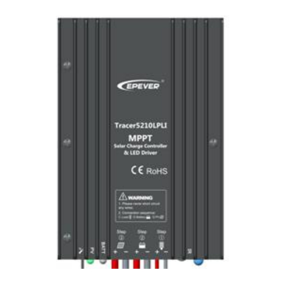
3. Product Features
Temperature Sensor
①
PV Positive and Negative Wires
②
Battery Positive and Negative Wires
③
Load Positive and Negative Wires
④
4. Wiring
Reference for Serial connection of LED
System
Serial
Voltage
connection
12V
5~18 LED
24V
10~18 LED
NOTE: The above LED (1W, 3.3V) is calculated. If the user uses the
unconventional LED, The actual LED voltage must be less than the Max.
Load Output Voltage.
WARNING: Risk of electric shock! With the product's built-in boost LED
driver, the output voltage is higher than the human safety voltage.
Connection Order
1) Connect components to the charge controller in the sequence as shown above and
pay much attention to the "+" and "-." Please don't insert the fast-acting fuse or turn on
the breaker during the installation. When disconnecting the system, the order will be
---with built-in LED Driver
Charging Status LED indicator
⑤
Battery Status LED indicator
⑥
Infrared Receiver Module
⑦
Infrared LED
⑧
Min. Output
Max. Output Voltage
Voltage
15V
60V
30V
60V
1
Tel: +86-752-3889706
reserved.
2) After powering on the controller, check the battery LED indicator on the controller; it
will be green. If it's not green, please refer to chapter 9.
3) Connecting a fast-acting fuse in series through battery positive (+) in the circuit and
the battery circuit fast-acting fuse must be 1.25 to 2 times the rated current. The
installed distance is within 150mm.
NOTE: The controller can only charge or discharge alone but can carry
out the discharge process to check the load preferentially.
Load self-test function
The load is ON when the controller is powered on for 10 seconds. After 10 seconds, it
restores to set working mode.
5. LED Indicators
Indicator
Color
Green
On Solid
Green
OFF
Green
Slowly Flashing(1Hz)
Green
Fast Flashing(4Hz)
Green
On Solid
Green
Slowly Flashing(1Hz)
Green
Fast Flashing(4Hz)
Orange
On Solid
Red
On Solid
Red
Fast Flashing(4Hz)
Charging indicator(green) and battery
indicator(orange) flash twice
Charging indicator(green) and battery
indicator(orange) fast flash simultaneously
※ When the battery type is a lithium battery, the controller cannot recognize the
system voltage automatically.
6. Load Working Mode
1) Manual Mode
2) Light ON/OFF(Default)
3) Light ON + Timer
Light ON + Timer1
Light ON + Timer2
Light ON + Timer3
4) Real-time Control
Control the load ON/OFF by setting a real-time clock.
5) Intelligent Power Reduction Mode
When the battery voltage goes lower than the "Reduce Power Start Voltage
(adjustable)," the intelligent power reduction mode is enabled. The LED output current is
automatically reduced linearly with the battery's voltage drop. When the battery voltage
goes lower than the "Reduce Power End Voltage (adjustable)," the LED output current
is 2% of the rated load current. The minimum percentage can be set to 1%. Also, when
Website: www.epever.com
Status
Instruction
PV connection normal but
low voltage(irradiance) from
PV, no charging
No PV voltage(night time)
or PV connection problem
In charging
PV Over voltage
Normal
Full
Overvoltage
Under voltage
Over discharged
Low temperature
Battery Overheating
Set parameters
successfully
System voltage error※
Turn-On voltage (Adjustable):
5V (12Vsystem), delay10min.
Turn-Off voltage (Adjustable):
6V (12Vsystem), delay10min.
Note: 24V system voltage×2
2
Advertisement

Related Manuals for Epever Tracer1305LPLI


Summary of Contents for Epever Tracer1305LPLI
- Page 1 HUIZHOU EPEVER TECHNOLOGY CO., LTD. Tel: +86-752-3889706 Website: www.epever.com reserved. ※ Thank you for selecting the Tracer LPLI series MPPT solar 2) After powering on the controller, check the battery LED indicator on the controller; it will be green. If it's not green, please refer to chapter 9.
- Page 2 HUIZHOU EPEVER TECHNOLOGY CO., LTD. Tel: +86-752-3889706 Website: www.epever.com the battery voltage exceeds "Reduce Power Start Voltage," the controller exits the gradually from T4 to T1, it is intelligent power reduction mode. performed at I4. NOTE: In Light ON/OFF and Light ON/Timer mode, the load is turned on after a Load current ≥2.5 times rated current...
Need help?
Do you have a question about the Tracer1305LPLI and is the answer not in the manual?
Questions and answers