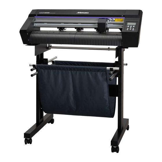
MIMAKI CG-60AR Operation Manual
Cutting plotter
Hide thumbs
Also See for CG-60AR:
- Installation instructions manual (8 pages) ,
- Safety precautions (12 pages) ,
- Care and maintenance (16 pages)

Related Manuals for MIMAKI CG-60AR


Summary of Contents for MIMAKI CG-60AR
- Page 1 You can also download the latest manual from official website. MIMAKI ENGINEERING CO., LTD. https://mimaki.com/ D203577-10 Original instructions...
-
Page 2: Table Of Contents
2.1 Cutting Process .............. 42 2.2 Loading a Sheet.............. 44 Loading a Leaf Sheet (Cut Sheet) ............ 47 Loading a Roll Sheet (CG-60AR) ............ 48 Loading a Roll Sheet (CG-100/130AR) .......... 52 Pinch Roller Position/Number and Clamp Settings ...... 55 2.3 Installing Tools................ - Page 3 2.6 Test Cutting ................ 72 2.7 Cut the data................ 73 Setting the Origin ................ 73 Starting Cutting ................... 73 Pausing Cutting .................. 74 Aborting Cutting (Data Clear) ............. 74 Retracting the Carriage............... 74 2.8 Separating Sheets (Manual Cutting)........ 75 Chapter 3 Cutting Data with Register Marks 3.1 Process for Cutting Data with Register Marks ......
- Page 4 4.9 Other Useful Functions ............ 119 Sheet Feed .................. 119 Pause [HOLD]................... 119 Feed Settings [FEED OPTION] ............ 120 Preventing Uncut Media [OVER CUT/CORNER CUT]..... 121 Configuring the Network Settings [NETWORK]........ 122 Event Email Function Settings [EVENT MAIL] ......... 124 Outputting the Settings List [LIST] ............
- Page 5 Chapter 8 Dealing with Problems 8.1 Troubleshooting .............. 160 Checking Register Mark Sensor Responsiveness...... 162 Aligning the Register Mark Sensor Position ........ 164 Investigating the Cause of Cutting Failures ........ 165 8.2 Problems Indicated by Messages......... 167 Error Messages ................ 167 Display Message List................
-
Page 6: Introduction
© 2021 MIMAKI ENGINEERING Co., Ltd. l Disclaimers • Mimaki Engineering accepts no liability for damages arising directly or indirectly from the use of the CG- AR ("this machine" hereinafter), whether or not the product is faulty. • Mimaki Engineering rejects all liability for damages, direct or indirect, attributable to materials created while using this machine. - Page 7 Introduction • Use only the cables recommended by Mimaki Engineering when connecting to this product. Use of other cables may cause the product to exceed the restrictions stipulated by FCC regulations. To maintain compliance with FCC regulations, use the cables recommended by Mimaki...
-
Page 8: Product Description
"ID Cut Process"(P. 97) l Plug-in cutting software provided as standard The MIMAKI plug-in cutting software enables text and graphics edited in Illustrator to be cut easily and cleanly. "Installing Cutting Software and Plotter Driver"(P. 20) l Cutting using Windows plotter driver Using the Windows plotter driver allows cutting data to be output from applications such as Microsoft Word and Excel in addition to the MIMAKI SimplePOP design software. -
Page 9: To Ensure Safe Use
To ensure safe use To ensure safe use Symbols In this manual, the symbols indicate and explain precautions. Make sure you fully understand the meaning of each symbol and use the machine safely and correctly. Explanation WARNING Indicates a potential hazard that may result in death or serious injury if handled improperly or if instructions are disregarded. -
Page 10: Usage Precautions
To ensure safe use Usage Precautions l In the event of abnormal conditions • In the event of abnormal conditions such as smoke or unusual odor, turn off the main power immediately and unplug the power cable. Continuing to use the product under these conditions may result in failure, electric shock, or fire. - Page 11 To ensure safe use • Do not touch the rotating grit rollers. There is a risk of injury due to abrasion of the skin or fingernails of hands. • Keep parts of the body such as the face and hands away from moving parts. Also keep clothing (e.g., loose clothing and accessories) that may impede work away from the machine.
-
Page 12: Installation Precautions
Installation Precautions Installation Precautions • Do not install this machine in environments where flammable substances are present (e.g., gasoline, flammable spray, alcohol, thinner, lacquer, or powder). This machine is not explosion- proof. The product poses a risk of explosion. • Do not place vases, pot plants, cups, cosmetics, containers of chemicals or water, or small metal objects on top of this machine. -
Page 13: Installation Space
17 kg (27 kg)*1 35 kg 43 kg *1. The CG-60AR is not equipped with legs as standard. The dimensions in parentheses apply when the optional legs are fitted. The CG-100/130AR are equipped with legs as standard. 1,000 mm or more... -
Page 14: Warning Label
Make sure you fully understand the details indicated on the various warning labels. If any of the warning labels becomes dirty and illegible or peel off, contact your local dealer or our service office to request new warning labels. CG-60/100/130AR CG-60AR CG-100/130AR No. Order code Label... -
Page 15: Chapter 1 Before Using This Machine
Chapter 1 Before Using This Machine This chapter Describes items such as the individual part names with which operators should familiarize themselves before using this machine. Preparation ............16 Connect host computer to machine....3 3 Assembling the Legs and Sheet Basket ..16 Using a USB Cable ........ -
Page 16: Preparation
The "Assembly Procedure" can be downloaded from the following URL: https://mimaki.com/product/cutting/c-roll/cg-ar-series/download-manual.html • The legs for the CG-60AR are options available separately. Contact your local dealer or our service office. No "Leg Stand Assembly" video is provided for the CG-60AR. Read through the "Assembly Procedure"... - Page 17 Chapter 1 Before Using This Machine It is recommended that the cutter guard be attached if the sheet may be damaged by the cutter due to the sheet lifting during cutting. • Turn off the machine power supply before attaching or removing the cutter guard. •...
- Page 18 Chapter 1 Before Using This Machine Insert the cutter guard into the pen shaft. Pen shaft Cutter guard Rotate the cutter guard and engage the protrusion into the slot in the yoke-bracket. • Push in until it engages with a click. Yoke-bracket Reattach the carriage cover.
- Page 19 Chapter 1 Before Using This Machine (2) Lower the carriage cover until it is vertical, making sure it does not detach from the lugs. Carriage cover (3) Lift the carriage cover to push it into the lugs. Carriage cover (4) Reattach the screw into the screw hole in the carriage cover. •...
-
Page 20: Installing Cutting Software And Plotter Driver
Reattach the carriage cover. • "Reattach the carriage cover."(P. 18) Installing Cutting Software and Plotter Driver The following two Mimaki software applications are available for cutting: Software name Explanation Plug-in software allowing processes from design to cutting data creation and output to a cutting plotter to be performed within ®... -
Page 21: Installing The Firmware Updater
Updating enables issues such as faults with Mimaki products to be resolved. This software should be used to check the latest information. - Page 22 Chapter 1 Before Using This Machine • For more information on how to register Mimaki products and update the firmware version, click [Mimaki Firmware Updater] - [Firmware Version Update Guide] on the Windows menu, to read the manual. The latest version can be downloaded and viewed at the following URL:...
-
Page 23: Part Names And Functions
"Moving the Pinch Rollers"(P. 55) Grit roller Roll stay Holds the roll bar. "Loading a Roll Sheet (CG-100/130AR)"(P. 52) (The legs are options available separately for the CG-60AR.) Pen line Area in which printing and cutting is performed. "Pen Line Rubber Replacement"(P. 148) Platen The sheet is moved along the platen. - Page 24 Chapter 1 Before Using This Machine Name Outline 11 Pinch roller guide Indicates the pinch roller setting position. "Pinch Rollers and Grit marks Rollers"(P. 28) "Moving the Pinch Rollers"(P. 55) 12 SHEET sensor Detects whether a sheet is present and detects the sheet length. "SHEET sensor"(P.
-
Page 25: Rear
Prevents the roll sheet from rotating when loading a sheet. "Loading a Roll Sheet (CG-100/130AR)"(P. 52) (CG-100/130AR only) (The legs are options available separately for the CG-60AR.) Roll bars A roll sheet is loaded on top of the two bars. "Loading a Roll Sheet (CG-100/130AR)"(P. - Page 26 Chapter 1 Before Using This Machine Name Outline USB interface A USB interface connector. "Using a USB Cable"(P. 33) connector 10 LAN connector A LAN connector. "Using a LAN Cable"(P. 33) 11 AC inlet Used to connect the power cable (provided). "Connecting the Power Cable"(P.
-
Page 27: Carriage
Chapter 1 Before Using This Machine Carriage Name Outline LED pointer The red LED pointer lights up in the following situations: • Before sheet detection (Automatically goes out after sheet detection or if no sheet has been detected for 5 minutes.) •... -
Page 28: Pinch Rollers And Grit Rollers
Chapter 1 Before Using This Machine Pinch Rollers and Grit Rollers The pinch rollers and grit rollers are used to grip and feed the sheet. For more information, refer to "Moving the Pinch Rollers"(P. 55). For more information on the settings for the number of pinch rollers, refer to "Setting the Number of Pinch Rollers to Use"(P. -
Page 29: Tray
Chapter 1 Before Using This Machine Tray Tray used for placing small items such as retractable knives. • Retractable knives and cutters are dangerous. Keep out of the reach of children. • Do not place heavy items on the tray. Heavy items may cause the cover to deform and make contact with the carriage. -
Page 30: Operating Panel
Chapter 1 Before Using This Machine Operating panel This is used to control the product and make/change settings. can be used to operate the machine remotely from a computer or smartphone. For more information, refer to online help. • The keys are designed for finger input. Do not use sharp or pointed objects, as this may damage the keys. - Page 31 Chapter 1 Before Using This Machine Before sheet detection After sheet detection When selecting a When entering a setting function Detects sheet width Moves carriage to left and sheet front end Detects sheet width Moves carriage to right and sheet length Detects sheet width Moves sheet to rear of Returns to previous...
- Page 32 Chapter 1 Before Using This Machine Display Outline FUNC Pressing the [FUNC1] key displays the setting screens. TOOL Pressing the [FUNC2] key displays the tool condition selection screen or tool condition setting screen. REMOTE Pressing the [FUNC3] key switches from local mode to remote mode.
-
Page 33: Connect Host Computer To Machine
Using a USB Cable Connect a host computer to this machine using a USB interface cable. The Mimaki USB driver is required when connecting using a USB cable. The USB driver can be installed when setting up . For more information, refer to the reference guide. -
Page 34: Using An Rs-232C Cable
Chapter 1 Before Using This Machine l Network Connection Precautions Make sure the network is set up as follows: Cutting will not be possible if the network is not set up correctly. • Use a Category 5 or higher LAN cable. •... - Page 35 Chapter 1 Before Using This Machine Press to select the following communication conditions, then press the [ENTER/HOLD] key. • Communication conditions: Data bits, parity, stop bit, handshake, step size, close time Press to select the setting, then press the [ENTER/HOLD] key. •...
-
Page 36: Connecting The Power Cable
Chapter 1 Before Using This Machine 1.4 Connecting the Power Cable Check to confirm that the machine power supply is off. • "Turning Off the Power"(P. 38) Attach the power cable clamp (accessory). • Insert the power cable clamp into the power cable clamp hole. •... - Page 37 Chapter 1 Before Using This Machine Pass the power cable through the power cable clamp to secure it in place. Power cable Power cable clamp Slide the power cable clamp in. Power cable Power cable clamp Plug the power plug into the power outlet. •...
-
Page 38: Turning On The Power
Chapter 1 Before Using This Machine Turning On the Power • Before turning on the power, check to confirm that the pinch rollers are raised. • Turn on the host computer first, then turn on power switch for this machine on. A malfunction may occur if power is not turned on in this sequence. - Page 39 Chapter 1 Before Using This Machine Shut down the computer connected to the machine.
-
Page 40: System Configuration
Chapter 1 Before Using This Machine 1.5 System Configuration This machine cuts using cutting data created with applications such as and SimplePOP. [Ethernet connection] Host computer [Local network] Cutting data sent Cutting instructions... -
Page 41: Chapter 2 Cutting
Setting Tool Conditions ........6 9 Loading a Leaf Sheet (Cut Sheet)....47 Test Cutting ............7 2 Loading a Roll Sheet (CG-60AR)....48 Cut the data............7 3 Loading a Roll Sheet (CG-100/130AR)..52 Setting the Origin ......... 7 3 Pinch Roller Position/Number and Clamp Starting Cutting .......... -
Page 42: Cutting Process
Chapter 2 Cutting 2.1 Cutting Process Start up host computer (computer on which the cutting software is installed). Connect host computer to machine. "Using a USB Cable"(P. 33) "Using a LAN Cable"(P. 33) "Using an RS-232C Cable"(P. 34) Turn on the power. "Turning On the Power"(P. - Page 43 Chapter 2 Cutting Separate sheets. Cut the sheets manually. "Separating Sheets (Manual Cutting)"(P. 75) Turn off machine power. "Turning Off the Power"(P. 38)
-
Page 44: Loading A Sheet
Load a leaf sheet (cut sheet) or roll sheet, then pull the clamp lever toward you to clamp the sheet between the pinch and grit rollers. For more information, refer to "Loading a Roll Sheet (CG-60AR)"(P. 48) "Loading a Roll Sheet (CG-100/130AR)"(P. 52) "Loading a Leaf Sheet (Cut Sheet)"(P. - Page 45 Chapter 2 Cutting Rear non-plotting [Expand off] area * Non-plotting area 30mm Area where cutting is Pinch roller not possible Cut length 5mm or more Front non-plotting area 20mm Cut width Origin Rear non-plotting [Expand on] area 30mm Pinch roller Cut length 5mm or more Front non-plotting...
- Page 46 Chapter 2 Cutting Sheet detection can be performed using any of the following five methods. [END] Roll sheet set to rear Leaf sheet set to rear Sheet width detection only Detection Sheet width detected, then Sheet width detected, then Sheet width detected method sheet front edge detected sheet front and rear edges...
-
Page 47: Loading A Leaf Sheet (Cut Sheet)
Chapter 2 Cutting Loading a Leaf Sheet (Cut Sheet) Push back the clamp lever to raise the pinch rollers. Pass the sheet through the platen. • Insert the sheet between the pinch rollers and the grit rollers. • Either align the right edge of the sheet, using the vertical ribs on the platen, or align the front of the sheet to be parallel with the platen. -
Page 48: Loading A Roll Sheet (Cg-60Ar)
Loading a Roll Sheet (CG-60AR) When using a roll sheet, the roll-placing tables or optional CG-60AR legs must be attached. l Attach the roll-placing tables. Insert the roll-placing table into the slot at the rear of the machine. - Page 49 Attach the other roll-placing table to the machine in the same way. Adjust the roll-placing table positions to suit the roll width. l Attach the optional CG-60AR legs. For more information on how to attach the optional CG-60AR legs, refer to the assembly instructions provided with the legs.
- Page 50 Chapter 2 Cutting l Load a roll sheet. Place a roll sheet on the roll-placing tables or roll bars (the legs are optional). • Be sure to mount with the sheet facing in the correct direction. No Good Push back the clamp lever to raise the pinch rollers. Pass the sheet through the platen.
- Page 51 Chapter 2 Cutting Set the clamps at both edges to High mode. • "Setting the Clamp High/Low Mode"(P. 57) If using three pinch rollers, select High mode or Low mode for the center clamp as appropriate to suit the sheet being used. •...
-
Page 52: Loading A Roll Sheet (Cg-100/130Ar)
Chapter 2 Cutting Press to select the number of pinch rollers to be used. • If [ROLL. SELECT] is set to [ON], select the number of pinch rollers to use. "Setting the Number of Pinch Rollers to Use"(P. 56) Start sheet detection. •... - Page 53 Chapter 2 Cutting • Check that the roll bars have been installed level. • When moving roll bars to different slots, keep them level when lifting them. There is a risk of damaging the roll stay assembly if the roll bars are lifted at an angle. Clamp the roll sheet using the roll holders.
- Page 54 Chapter 2 Cutting Pass the sheet through the platen. • Insert the sheet between the pinch rollers and the grit rollers. • Align the right edge of the sheet using the vertical ribs on the platen. Vertical rib Move the pinch rollers to suit the sheet width. •...
-
Page 55: Pinch Roller Position/Number And Clamp Settings
Chapter 2 Cutting Check to confirm that the pinch rollers are evenly spaced. • Hold the sheet between the pinch rollers and grit rollers. • If the spacing is not uniform, repeat all steps from the start. Unlock the roll stopper •... - Page 56 Chapter 2 Cutting For more information on the settings for the number of pinch rollers, refer to "Setting the Number of Pinch Rollers to Use"(P. 56). For more information on the sheet clamping pressure, refer to "Clamp"(P. 28). Pinch roller 2 Pinch roller 1 Pinch roller guide marks •...
- Page 57 Chapter 2 Cutting Press to select the number of pinch rollers to detect, then press the [ENTER/HOLD] key. • Number of pinch rollers: 2, 3 Press to select the [ROLL.SELECT] setting, then press the [ENTER/HOLD] key. • Settings: ON/OFF • Select [ON] to display the screen for selecting the number of pinch rollers to be used in sheet detection.
- Page 58 Chapter 2 Cutting Be sure to push back the clamp lever to raise the pinch rollers before enabling or disabling the center clamp. Center clamp enabled: Raise pinch roller Center clamp disabled: Lower pinch roller Three pinch rollers should always be used when using the maximum sheet width of the machine. Enable or disable the center clamp as necessary for the middle pinch roller.
-
Page 59: Installing Tools
Chapter 2 Cutting 2.3 Installing Tools This machine can be used with the following tools: • Cutter (for cutting) Used to cut the printed image on a sheet or to cut characters with the cutting sheet. "Using the Cutter"(P. 59) •... - Page 60 Chapter 2 Cutting • If the base paper is thinner than the label film: As far as to cut into label film Label film Cutting blade Cut amount protrusion length Base paper • The protrusion of the cutting blade can be adjusted accurately using the optional cutting blade adjuster tool.
- Page 61 Chapter 2 Cutting Insert the cutter holder into the tool holder. (1) Push the brim of the cutter holder against the tool holder. (2) Put the brim of the cutter holder into the tool holder. Brim Holder presser Secure the cutter holder. •...
- Page 62 Chapter 2 Cutting Adjusting the Cutting Blade Protrusion Length Turn the adjusting knob to adjust the protrusion of the cutting blade. • Turn the adjusting knob in the direction indicated by the arrow in the picture to have the blade protrude.
-
Page 63: Using A Pen
Chapter 2 Cutting Fix the lock nut by turning in the direction indicated by the arrow in the picture. Adjusting the Cutting Blade Protrusion Length Loosen the lock nut of the cutter holder. Lock nut Turn the adjusting knob to adjust the protrusion of the cutting blade. Adjusting knob Fix the lock nut by turning in the direction indicated by the arrow in the picture. - Page 64 Fix the cap by turning in the direction indicated by the arrow in the picture. Installing a (Supply) Ballpoint Pen in the Pen Adapter (SPA-0169) Use a ballpoint pen with a diameter of 8 to 9 mm. The ballpoint pen type may affect image quality. Use a ballpoint pen supplied by Mimaki.
- Page 65 Chapter 2 Cutting Put the cap on the pen adapter. • The cap is used to adjust the height of the pen nib. Pen adapter Insert the ballpoint pen into the pen adapter. • Insert the pen nib until it hits the cap. Ballpoint pen Fix the pen nib by turning the knob screw in the direction indicated by the arrow in the picture.
- Page 66 Chapter 2 Cutting Remove the cap. Installing a Pen Turn the knob screw and loosen the holder presser. Holder presser Knob screw Insert the pen holder or pen adapter into the tool holder. (1) Push the brim of the pen holder or pen adapter against the tool holder. •...
-
Page 67: Using The Creasing Tool
Chapter 2 Cutting Using the Creasing Tool Be sure to use the optional sheet table and cutting sheet when creasing. "Sheet Tables and Cutting Sheet"(P. 152) Installing the Creasing Tool Turn the knob screw and loosen the holder presser. Holder presser Knob screw Insert the creasing tool into the tool holder. -
Page 68: Selecting Tool Conditions
Chapter 2 Cutting 2.4 Selecting Tool Conditions Before starting cutting (or printing), select the tool conditions to suit the sheet and tool being used. Press the [TOOL] key on the local mode screen. Press the [TOOL] key to select the required tool conditions. •... -
Page 69: Setting Tool Conditions
Chapter 2 Cutting 2.5 Setting Tool Conditions Set the cutting speed and pressure to match the type of sheet and tools used. Tool Item SPEED PRESS OFFSET HALF CUT1 to 6 Cutting speed Cut pressure Offset Half cut Print Printing speed Pen pressure Speed Pressure... - Page 70 Chapter 2 Cutting Press . (for cutting only) • The cursor moves to the half cut setting (HALF). Press to enable or disable half cut. (for cutting only) • When enabled, a dotted line is cut without cutting out the base paper. Set the following items when this is enabled.
- Page 71 Chapter 2 Cutting Item Messag Tool Setting Step size Outline Pressur PRES Cutter/ 10 to 550 2 g (10 to • Sets the pressure for cutting, creasing, or pen creasin 20 g) writing. 5 g (25 to • This setting is also required for half cuts. 100 g) 10 to 150 10 g (110...
-
Page 72: Test Cutting
Chapter 2 Cutting 2.6 Test Cutting Execute test cutting to confirm that the tool conditions are set appropriately. Cutting can be improved by increasing the pressure, as the cutter blade grows dull with wear. This is only a temporary measure. We recommend replacing the cutter blade to maintain cutting quality. Press the [FUNCTION] key on the local mode screen to select [SQUARE CUT]. -
Page 73: Cut The Data
Chapter 2 Cutting 2.7 Cut the data. Cutting software is required to cut data. For more information on cutting software, refer to "Installing Cutting Software and Plotter Driver"(P. 20). Check beforehand • Were the pinch roller positions adjusted? "Pinch Rollers and Grit Rollers"(P. 28) •... -
Page 74: Pausing Cutting
Chapter 2 Cutting Pausing Cutting Press the [REMOTE] key while cutting is in progress. • Cutting is paused. • If data is being sent from a PC, data transmission is paused at the PC. Press the [REMOTE] key. • Cutting resumes. •... -
Page 75: Separating Sheets (Manual Cutting)
Chapter 2 Cutting 2.8 Separating Sheets (Manual Cutting) Cutting slot Press down on the sheet with your hand. • Press down firmly to prevent the sheet lifting up while cutting. Cut the sheet. • Cut the sheet along the cutting slot on the platen using a retractable knife. - Page 76 Chapter 2 Cutting...
-
Page 77: Chapter 3 Cutting Data With Register Marks
Chapter 3 Cutting Data with Register Marks This chapter Describes the register mark creation conditions and basic information. Process for Cutting Data with Register Marks.78 Detect register marks........8 9 Checking Sheet Tilt Using the LED Pointer . 8 9 Creating Register Marks........80 Detecting Register Marks Using Full- Register Marks ........... -
Page 78: Process For Cutting Data With Register Marks
Chapter 3 Cutting Data with Register Marks 3.1 Process for Cutting Data with Register Marks Printing images to be used as labels with "register marks" allows sheets to be cut by detecting the register mark positions. Create data with register marks. "Creating Register Marks"(P. - Page 79 Chapter 3 Cutting Data with Register Marks Mark shape Type 1 Type 2 Register mark Register mark detection start detection start position position Cut the data. "Cut the data."(P. 73) Cut the sheet. "Separating Sheets (Manual Cutting)"(P. 75)
-
Page 80: Creating Register Marks
Chapter 3 Cutting Data with Register Marks 3.2 Creating Register Marks Printing image data with "register marks" can increase cutting accuracy and quality. There are some limitations to register marks. Read the following thoroughly before creating register marks. Trimming register marks cannot be used with this machine. Register Marks The following two types of register marks can be used with this machine: Mark shape... -
Page 81: Register Mark Size
2,001 mm or more 35 to 40 mm • If the "Fill around the register mark" function of the Mimaki cutting software is enabled, the register mark length (B) should be 10 mm or more. When Printing Register Marks Continuously The register mark length (B) should be 8 mm or more. -
Page 82: Spacing Between Register Marks
Chapter 3 Cutting Data with Register Marks Spacing Between Register Marks The spacing between register marks (D) is as shown below. Mark shape Type 1 Type 2 Register mark spacing (D): Register mark length (B) Register mark spacing (D): Register mark length (B) ×... - Page 83 This machine can detect register marks in the range shown in the above figure. l ID Cut For more information on ID cut, refer to "ID Cut Process"(P. 97) and the ID Cut Guide. The ID Cut Guide can be downloaded from the official Mimaki website. (https://mimaki.com/download/)
-
Page 84: Plotting Areas Around Register Marks
Chapter 3 Cutting Data with Register Marks No-Plotting Areas Around Register Marks Do not plot data around register marks. The mark origins may be identified incorrectly, or the machine may fail to detect the register marks. Mark shape Type 1 Type 2 〃... -
Page 85: Setting Register Mark Detection Conditions
Chapter 3 Cutting Data with Register Marks 3.3 Setting Register Mark Detection Conditions Press the [FUNCTION] key in local mode. Press the keys to select [SET UP], then press the [ENTER/HOLD] key. • [MARK DETECT] appears on the screen. Press the [ENTER/HOLD] key. •... - Page 86 Chapter 3 Cutting Data with Register Marks l Scale compensation setting [DIST.REVI.] • When cutting using , set [DIST.REVI.] to [OFF]. Setting Details Scale compensation is not input for register mark detection. BEFORE Scale compensation and trapezoidal correction values are entered before register mark detection.
- Page 87 Chapter 3 Cutting Data with Register Marks Setting Details Register mark: Type 1 Register mark: Type 2 l COPIES A (UP) and COPIES B (LEFT) settings [COPIES A (↑) and COPIES B (<-)] Setting Details 1 to 9999 This is enabled when the same pattern is printed in multiple with uniform spacing. (COPIES A) The specified number of patterns is cut while continuously reading the register marks based on the first data.
- Page 88 Chapter 3 Cutting Data with Register Marks Setting Details reading resumes. Register mark detection start position Set to [OFF] if checking is not required. l Detection mode setting [DETECT MODE] Setting Details High Speed Register mark lines are scanned bi-directionally to determine the position. Detection time is reduced, but accuracy is also reduced.
-
Page 89: Detect Register Marks
Chapter 3 Cutting Data with Register Marks 3.4 Detect register marks. Register marks can be detected using either full-automatic or semi-automatic detection. Detect using semi-automatic detection in cases where TP1 is not at the bottom right of the sheet or when using . -
Page 90: Detecting Register Marks Using Full-Automatic Detection
Chapter 3 Cutting Data with Register Marks Detecting Register Marks Using Full-Automatic Detection The distance between register marks detected by the plotter is adjusted against the distance between the register marks printed on the sheet. First, measure the distances (A and B) between the register marks in the data. Measure between the register mark center points. - Page 91 Chapter 3 Cutting Data with Register Marks Set using • Press the [ENTER/HOLD] key to proceed to the next scale compensation setting. • If [MARK DETECT] is set to [2ptA], the screen for entering distance B does not appear. • If [MARK DETECT] is set to [2ptB], the screen for entering distance A does not appear. •...
-
Page 92: Detecting Register Marks Using Semi-Automatic Detection
Chapter 3 Cutting Data with Register Marks Press the [ENTER/HOLD] key. • Only the sheet width is detected, after which register mark detection starts. • If [ROLL. SELECT] is set to [ON], select the number of pinch rollers to be used. "Setting the Number of Pinch Rollers to Use"(P. - Page 93 Chapter 3 Cutting Data with Register Marks Detection procedure using front specification Load the sheet, then pull the clamp lever toward you. • The sheet is held by the pinch rollers. Press to start sheet detection. (Load from rear) • If [ROLL. SELECT] is set to [ON], select the number of pinch rollers to be used. "Setting the Number of Pinch Rollers to Use"(P.
- Page 94 Chapter 3 Cutting Data with Register Marks to set the scale correction value. • Press the [ENTER/HOLD] key to proceed to the next scale compensation setting. • If [DIST.REVI.] is set to [OFF], the screen for setting scale compensation does not appear. •...
-
Page 95: Detecting Register Marks Automatically After Sheet Detection
Chapter 3 Cutting Data with Register Marks Once the register marks have been detected, set using the scale compensation setting screen. • The following example shows the procedure for four-point detection. (1) Set using if the detected register mark distances differ from the measured values. (2) Press the [ENTER/HOLD] key to proceed to the next scale compensation setting. - Page 96 Chapter 3 Cutting Data with Register Marks to select the width to be scanned, then press the [ENTER/HOLD] key. • Setting: 10 to 30 cm to select the search range, then press the [ENTER/HOLD] key. • Setting: 10 to 50cm Press the [END] key several times to exit.
-
Page 97: Id Cut Process
Chapter 3 Cutting Data with Register Marks 3.5 ID Cut Process • For more information, refer to the ID Cut Guide. https://mimaki.com/download/software.html For information on the ID cut register mark scanning range, refer to "This machine can detect register marks in the range shown in the above figure."(P. - Page 98 Chapter 3 Cutting Data with Register Marks...
-
Page 99: Chapter 4 Helpful Tips
Chapter 4 Helpful Tips This chapter Describes the register mark creation conditions and basic information. Jog Mode Functions ........100 Other Useful Functions........1 19 2-Point Line Correction [AXIS CORRECT] Sheet Feed ..........1 19 ..............100 Pause [HOLD]..........1 19 Cut Area Setting [CUT AREA].... -
Page 100: Jog Mode Functions
Chapter 4 Helpful Tips 4.1 Jog Mode Functions The jog keys can be used to switch from local mode to jog mode. Jog mode allows the following items to be set or executed. Function name Details Reference page Origin setting Sets the cutting (printing) start position. -
Page 101: Cut Area Setting [Cut Area]
Chapter 4 Helpful Tips Cut Area Setting [CUT AREA] The cut area is set by the range extending from the origin to the diagonally opposite UL (upper left) point set by the user. Set the UL point position here. Repeating sheet detection will clear the cut area. Point UL AREA Origin... - Page 102 Chapter 4 Helpful Tips to move the pen nib to the desired point on the print. • The coordinates from the origin are displayed. • Reducing the step units with the jog step function enables the point to be specified more precisely. "JOG STEP"(P.
-
Page 103: Length Correction [Dist.comp.]
Settings: • Standard value A direction: 500, 1000, 1500, 2000, 2500 (mm) B direction (CG-60AR): 200, 400, 600 (mm) B direction (CG-100AR): 200, 400, 600, 800, 1000 (mm) B direction (CG-130AR): 200, 400, 600, 800, 1000, 1200 (mm) • Correction value A direction: ±... - Page 104 Chapter 4 Helpful Tips to select the distance correction number to be saved, then press the [ENTER/HOLD] key. • The previously corrected standard length (mm) is displayed. • If length correction has never been performed, the minimum standard length will be displayed. •...
- Page 105 Chapter 4 Helpful Tips Press the [ENTER/HOLD] key to confirm the AR direction correction value. • This can also be confirmed by pressing the key. • The AL direction standard length can now be set. If the measurement differs from the standard value, use to alter the AL correction value.
-
Page 106: Cutting Multiple Copies Of The Same Data [No. Copies]
Chapter 4 Helpful Tips 4.3 Cutting Multiple Copies of the Same Data [No. COPIES] You can cut the data stored in the receive buffer of the machine by the specified number (up to 999 sheets). • The last cutting data is stored in the receive buffer. When new data is received, the already saved data is overwritten. - Page 107 Chapter 4 Helpful Tips • If the origin mode is set to "CENTER", the intended cutting results may not be achieved. With multiple sheet cutting, it is recommended to set the origin to "Low-R". If the center origin is used, the data size will extend from the minimum cutting range position to the diagonally opposite maximum data size (range indicated by broken red line), resulting in excessive margins for data, as shown in the figure.
-
Page 108: Expanding The Cutting Area [Expands]
Chapter 4 Helpful Tips 4.4 Expanding the Cutting Area [EXPANDS] The cutting (printing) area can be expanded to reduce non-printing areas. (Expand function) Expanding the cutting area allows non-printing areas at the front and sides to be reduced by 10 mm. EXPANDS: OFF EXPANDS: ON Right pinch roller... -
Page 109: Selecting The Cutting Movement Direction [Rotation]
Chapter 4 Helpful Tips 4.5 Selecting the Cutting Movement Direction [ROTATION] Set the origin position and direction of the coordinate axes to match the application software being used. (Rotation function) Rotation not set Rotation set Origin Origin The carriage stops at the origin position after sheet detection. •... - Page 110 Chapter 4 Helpful Tips l Note about coordinate systems This machine uses the following four coordinate systems, in accordance with the combination of sheet loading direction and rotation function: [0° rotation] [90° rotation] ROTATION: OFF ROTATION: ON Sheet rear loading Sheet rear loading [180°...
-
Page 111: Divided Cutting [Divisioncut]
Chapter 4 Helpful Tips 4.6 Divided Cutting [DIVISIONcut] Setting divided cutting in the width (Y) direction allows data larger than the sheet width to be divided and cut. (Divided cutting function) Similarly, setting divided cutting in the feed (X) direction allows long data to be divided and cut, minimizing cutting deviations due to sheet meandering. -
Page 112: Y Direction (Width Direction) Divided Cutting
Chapter 4 Helpful Tips Y Direction (Width Direction) Divided Cutting Setting Y Direction (Width Direction) Divided Cutting Press the [FUNCTION] key in local mode. to select [SET UP], then press the [ENTER/HOLD] key. to select [DIVISIONcut], then press the [ENTER/HOLD] key. to select [Y], then press the [ENTER/HOLD] key. - Page 113 Chapter 4 Helpful Tips When [FRAME CUT] or [MARK CUT] is set to [ON] • Once cutting is complete, the frame and overlap margin marks will be automatically cut. Overlap margin mark Frame • The display indicates the time remaining until frame and mark cutting is complete. •...
-
Page 114: Direction (Feed Direction) Divided Cutting
Chapter 4 Helpful Tips X Direction (Feed Direction) Divided Cutting Setting X Direction (Feed Direction) Divided Cutting The data size in the feed direction will be cut divided at the positions corresponding to [Division Length + Cross Cut Length]. Setting the cross cut length cuts at the [Cut Length] position overlapping by the amount of the setting. Cross Cut Length Cut length Division... - Page 115 Chapter 4 Helpful Tips Cutting Data Using X Direction (Feed Direction) Divided Cutting Receive the data from the computer. • Cutting starts. • Long data is automatically divided, and each division length is cut by feeding the length to be cut. •...
-
Page 116: Changing The Cutting Sequence [Sorting]
Chapter 4 Helpful Tips 4.7 Changing the Cutting Sequence [SORTING] Cutting data sent from the host computer can be reordered to change the cutting sequence. (Sorting function) If the order of data sent from the application software prevents data from being cut using a single cut, the cutting sequence can be altered to enable the data to be cut using a single cut. -
Page 117: Setting Sorting
Chapter 4 Helpful Tips Setting Sorting Press the [FUNCTION] key in local mode. to select [SET UP], then press the [ENTER/HOLD] key. to select [SORTING], then press the [ENTER/HOLD] key. to select [ON], then press the [ENTER/HOLD] key. to select the [AUTO FEED] setting, then press the [ENTER/HOLD] key. •... -
Page 118: Operating The Main Unit Panel Remotely [R.contrl]
• is a remote access tool that allows information collection and panel operations from locations other than at the Mimaki printer or plotter. For more information, refer to online help. https://mimaki.com/manual/mimaki-remote-access/online_help/ When is being used, "During remote control. [ent]" is displayed on the display and the keys on the machine operating panel are disabled. -
Page 119: Other Useful Functions
Chapter 4 Helpful Tips 4.9 Other Useful Functions Sheet Feed The sheet can be pulled out in advance before cutting (or printing). This allows any sheet skew to be checked and prevented. • High-speed cutting with a roll sheet still rolled up may result in errors if the sheet drive is unable to keep up. -
Page 120: Feed Settings [Feed Option]
Chapter 4 Helpful Tips • The [ENTER/HOLD] becomes available once sheet detection has ended. • In local mode, hold down the [ENTER/HOLD] key for at least approximately 2.5 seconds. Feed Settings [FEED OPTION] Various feed related settings can be set. Function name Outline Refer to... -
Page 121: Preventing Uncut Media [Over Cut/Corner Cut]
Chapter 4 Helpful Tips Press the [END] key several times to exit. PRE FEED Setting The following automatic sheet feed items can be set to be performed after sheet detection. Item Setting Initial Outline value Feed count OFF, 1 to 5 Sets the number of times the sheet is fed backward (times) and forward. -
Page 122: Configuring The Network Settings [Network]
Chapter 4 Helpful Tips l OVER CUT The machine cuts the media in front of the cutting start point by the set value. The media is overcut by the set value at the end point. OVER CUT: OFF OVER CUT: 0.1 to 1.0 mm l CORNER CUT When the OVER CUT setting value is entered, CORNER CUT is displayed. - Page 123 Chapter 4 Helpful Tips Item Details Setting AutoIP ON/OFF Select "ON" to use the IP address set by the AutoIP protocol. Note that DHCP takes priority if DHCP is set to "ON". IP Address Sets the machine's IP address. • This can be set when both [DHCP] and [AutoIP] are set to "OFF".
-
Page 124: Event Email Function Settings [Event Mail]
• Internet communication charges for email notifications, etc. are the responsibility of the customer. • Event emails may not be delivered if problems arise with the Internet setup or equipment. Mimaki rejects all liability for damages resulting from delivery failure or delay. - Page 125 Chapter 4 Helpful Tips Item Details Setting Authentication OFF/POP before Sets the SMTP server authentication method. SMTP/SMTP Auth. [Auth.] User Name Alphanumeric Sets the user name used for authentication. characters or symbols [User Name] • This can be set when [Auth.] is not set to "OFF". (Not more than 30) Pass Word Alphanumeric...
- Page 126 Chapter 4 Helpful Tips l Set the email address and subject. Press the [FUNCTION] key in local mode. to select [SET UP], then press the [ENTER/HOLD] key. to select [EVENT MAIL], then press the [ENTER/HOLD] key. to select [Mail Addr.], then press the [ENTER/HOLD] key. •...
- Page 127 Chapter 4 Helpful Tips to select [EVENT MAIL], then press the [ENTER/HOLD]. to select [Test], then press the [ENTER/HOLD] key. Press the [ENTER/HOLD] key on the [EXECUTE] screen. • The transmission results are displayed. • An error code will be displayed if the test email transmission is unsuccessful. Refer to the error code list and take appropriate action.
-
Page 128: Outputting The Settings List [List]
Chapter 4 Helpful Tips Error code Likely cause Corrective action 12*** The sender email address is • Set an email address corresponding to the server invalid. account. 13*** The email recipient could be • Check the email address. found Or the email address •... -
Page 129: Copying Settings From Other User Settings [Config Copy]
Chapter 4 Helpful Tips Copying Settings from Other User Settings [CONFIG COPY] Press the [FUNCTION] key in local mode. to select [SET UP], then press the [ENTER/HOLD] key. to select [CONFIG COPY], then press the [ENTER/HOLD] key. to select the user setting number to be copied, then press the [ENTER/HOLD] key. •... -
Page 130: Outputting Received Data As Ascii Code [Dump]
Chapter 4 Helpful Tips Outputting Received Data as ASCII Code [DUMP] Data can be sent from the host computer and printed as ASCII code. Dumping is possible via an interface to which the host computer is connected. Change the tool to a pen. •... - Page 131 Chapter 4 Helpful Tips Press the [END] key several times to exit.
- Page 132 Chapter 4 Helpful Tips...
-
Page 133: Chapter 5 Settings
Chapter 5 Settings This chapter Describes the individual settings. FUNCTION ............134 SET UP ............1 35... -
Page 134: Function
This corrects such discrepancies. • Standard value: A direction: 500, 1,000, 1,500, 2,000, 2,500 mm B direction (CG-60AR): 200, 400, 600 mm B direction (CG-100AR): 200, 400, 600, 800, 1,000 mm B direction (CG-130AR): 200, 400, 600, 800, 1,000, 1,200 mm •... -
Page 135: Set Up
Chapter 5 Settings Item Details Refer to ASCII DUMP Sends data from the ★host computer☆, and "Outputting Received Data as prints the data as ASCII code. ASCII Code [DUMP]"(P. 130) DISPLAY Selects the screen display language. "Selecting the Screen Display Language [DISPLAY]"(P. - Page 136 Chapter 5 Settings Item Details Setting • CENTER: Sets the command origin in the center of the available cutting area. • Low-R: Sets the command origin at the lower right of the available cutting area. EXPANDS ON/OFF Reduces dead space to expand the cutting (printing) area.
- Page 137 Chapter 5 Settings Item Details Setting [SHEET TYPE] "SHEET TYPE"(P. 140) • STANDARD: When using regular sheets • HEAVY: When using heavier sheets (The maximum cutting speed setting will be limited to 20 cm/s, and the tool will be moved at 20 cm/s even if the up speed is set to a value over 20 cm/s.) SORTING...
- Page 138 Chapter 5 Settings Item Details Setting If curved cutting lines become crooked, set to "SLOW" to reduce the cutting speed on curved line segments. Up height 50%, 75%, 100% Sets the height when the tool is raised. The height to which the tool is raised from the down [UP HIGHT] position is specified as a percentage of the approximate stroke.
- Page 139 Chapter 5 Settings l Origin selection [ORGN SELECT] The origin position will be as follows when the rotation function is enabled: [Rotation disabled] Command origin With "Low-R" selected With "CENTER" selected [Rotation enabled] With "Low-R" selected With "CENTER" selected • Setting the command origin to "Low-R" when using roll sheet expands the cutting area to up to 51 m. •...
- Page 140 Chapter 5 Settings l JOG STEP Jog step should be set to determine an accurate position in the following cases: • When using two-point line correction "2-Point Line Correction [AXIS CORRECT]"(P. 100) • When setting an origin at an accurate position l DUMMY CUT Dummy cutting will not be performed if "PEN"...
-
Page 141: Chapter 6 Maintenance
Chapter 6 Maintenance This chapter Performing maintenance on this machine according to its usage frequency will maintain accuracy and extend its service life. Please read the maintenance precautions thoroughly before carrying out maintenance on the machine. Maintenance Precautions ......142 Consumable Item Replacement ..... 1 47 Cutter Replacement ........ -
Page 142: Maintenance Precautions
Chapter 6 Maintenance 6.1 Maintenance Precautions • This machine includes parts that must be replaced periodically. We therefore recommend taking out a maintenance contract. We also recommend cleaning this machine and replacing consumable items to prevent quality defects and accidents. •... -
Page 143: Maintenance Items And Timing
"When Not in Use for Extended Periods"(P. 146) Items Required for Maintenance To order replacement consumable items, contact your local dealer or our service office. For more information on consumable items, refer to our website. https://mimaki.com/supply/cutting.html • Avoid storing this product in locations accessible to children. -
Page 144: Maintenance Procedure
Chapter 6 Maintenance 6.3 Maintenance Procedure Cover (Exterior) Cleaning • Do not allow liquids to get inside the product. Otherwise there is a risk of failure, electric shock, or fire. • For heavy soiling, wipe using a soft cloth soaked in dilute detergent and thoroughly wrung out. -
Page 145: Cleaning The Y-Bar Rail Surfaces
Chapter 6 Maintenance Cleaning the Y-Bar Rail Surfaces • Before use, be sure to gently wipe the four rail faces A to D shown in the following figure with a dry cloth to remove any dirt or dust. Dirt on the rails may cause abnormal noise and affect cutting quality. -
Page 146: Cleaning The Grit Rollers
Chapter 6 Maintenance Cleaning the Grit Rollers With use, the protrusions on the grit rollers may become clogged with paper dust from sheets, causing sheets to slip. To prevent this, visually check for any debris, and clean promptly. A brush (such as a toothbrush) should be used to clean the grit rollers. Use a small amount of alcohol if dirt is difficult to remove. -
Page 147: Consumable Item Replacement
To order replacement consumable items, contact your local dealer or our service office. For more information on consumable items, refer to our website. https://mimaki.com/supply/cutting.html • When disposing of the product, contact an industrial waste disposal operator or dispose of the product in accordance with the local laws and regulations. -
Page 148: Pen Line Rubber Replacement
Chapter 6 Maintenance Part name Quanti Note Pinch roller Retaining screw Not used during replacement. Curved E-ring Not used during replacement. E-ring Not used during replacement. O-ring Washer Not used during replacement. l Recommended replacement guide Replace the pinch rollers every month if used for approximately 12 hours per day. Replace the pinch rollers every two weeks if used 24 hours per day. - Page 149 Chapter 6 Maintenance Use tweezers to peel off the end of the pen line rubber. • Wipe off any adhesive remaining in the platen slot with alcohol. Attach the double-sided tape provided into the platen slot. Peel off the backing paper from the double-sided tape. Attach a new pen line rubber on top of the double-sided tape.
- Page 150 Chapter 6 Maintenance...
- Page 151 Chapter 7 Options This chapter Describes the various options. Sheet Tables and Cutting Sheet ....152 Cutting............1 54 Attaching the Sheet Tables ...... 152 Storing the Cutting Sheet......1 57 Loading a Sheet on the Cutting Sheet ..153...
-
Page 152: Chapter 7 Options
The sheet tables are attached to the machine as shown below and used to support the cutting sheet. The explanation here uses illustrations of the CG-60AR. The cutting sheet allows cutting and creasing on coated card (thin to medium thickness coated card recommended) and all types of cutting on various types of sheet. -
Page 153: Loading A Sheet On The Cutting Sheet
Chapter 7 Options Affix the provided mark stickers at the locations of the two recesses on the front for inserting the sheet tables. • Affix the mark stickers at the third and fifth recesses from the right. Affix the provided mark stickers at the locations of the two recesses on the rear for inserting the sheet tables. -
Page 154: Cutting
Chapter 7 Options • Take care not to touch the adhesive surface. • Retain the separator, as this will be used when storing the cutting sheet. Adhesive surface Peel off Cutting sheet Separator Affix the sheet to the adhesive surface of the cutting sheet. •... - Page 155 Chapter 7 Options Place the cutting sheet on top of the sheet tables, and pass it through to the platen. • Insert into the gap between the pinch rollers and the grid rollers. • Note the insertion direction of the cutting sheet. Insertion direction Sheet Adhesive surface...
- Page 156 Chapter 7 Options • Cutting and creasing will not be possible correctly in the following cases: Incorrect examples Pinch roller riding over Pinch roller riding over cutting sheet edge sheet edge Align the front of the cutting sheet with the straight line at the front of the machine as shown in the figure below.
-
Page 157: Storing The Cutting Sheet
Chapter 7 Options l Guideline Cutting and Creasing Condition List for Coated Card The conditions listed here are only guidelines and do not guarantee quality. Cutting quality may be reduced and the blade may become worn more quickly if conditions outside these ranges are used. - Page 158 Chapter 7 Options...
- Page 159 Chapter 8 Dealing with Problems This chapter This chapter explains procedures for troubleshooting and addressing messages on the display. Troubleshooting..........160 Investigating the Cause of Cutting Failures Checking Register Mark Sensor ..............1 65 Responsiveness........162 Problems Indicated by Messages ....1 67 Aligning the Register Mark Sensor Position Error Messages..........
-
Page 160: Chapter 8 Dealing With Problems
For information on troubleshooting, refer to this chapter. Refer to the following URL for frequently asked questions (FAQs) about this product and customer support videos. https://mimaki.com/support/ If the recommended corrective action does not resolve the problem, contact your local dealer or our service office. - Page 161 Chapter 8 Dealing with Problems Symptom Cause Corrective action The clamping force (High/Low Select the correct clamping force. mode) has not been correctly "Clamp"(P. 28) selected. The roll sheet is loosely wound When loading the roll sheet, adjust the roll with slack present, causing the slack and parallel of the roll edges before sheet to meander or become...
-
Page 162: Checking Register Mark Sensor Responsiveness
Chapter 8 Dealing with Problems Checking Register Mark Sensor Responsiveness • Responsiveness cannot be checked accurately by moving the head and sheet manually. Be sure to check the register mark sensor responsiveness using the following procedure: • For information on creating register marks, refer to "Creating Register Marks"(P. - Page 163 Chapter 8 Dealing with Problems Press the [ENTER/HOLD] to start detection. • The machine automatically detects the lines in the X and Y directions (automatic detection operation: plus X direction > minus X direction > plus Y direction > minus Y direction). X direction Y direction •...
-
Page 164: Aligning The Register Mark Sensor Position
Chapter 8 Dealing with Problems Check the following again. • "Checking Register Mark Sensor Responsiveness"(P. 162) • If the buzzer does not sound four times, check the printed register mark conditions and contact your local distributor, our sales office, or service center. Aligning the Register Mark Sensor Position The offset between the cutter and register mark sensor can be adjusted. -
Page 165: Investigating The Cause Of Cutting Failures
Chapter 8 Dealing with Problems to select [SENSOR OFS], then press the [ENTER/HOLD] key. • After (one) register mark has been detected, auxiliary lines are cut for the register mark center lines together with five auxiliary lines at 0.2 mm intervals on either side of the center lines. +0.2 mm offset from register mark center lines in both A and B directions A direction... - Page 166 Chapter 8 Dealing with Problems l Sample Cut Results • Sample data can be cut properly, but not other data. – There is a problem with the host computer. • Sample data as well as other data cannot be cut properly. (When the start/end points remain uncut) –...
-
Page 167: Problems Indicated By Messages
Chapter 8 Dealing with Problems 8.2 Problems Indicated by Messages If a problem occurs, a message will appear on the display. Take appropriate measures based on the message. If a message is displayed again even after you take the recommended corrective action, contact your local dealer or our service office. Error Messages Check the error details in the following table corresponding to the error numbers displayed: If the problem persists even after carrying out the corrective action corresponding to the error number,... - Page 168 Chapter 8 Dealing with Problems Error Message Cause Corrective action number BUFFER • An error occurred in the receive buffer. POWER • An error occurred related to the motor. Commands • Received a code other Check the following points: than a COMMAND code. Clear the data and resend.
- Page 169 Chapter 8 Dealing with Problems Error Message Cause Corrective action number Check to confirm there are no errors in the mark detection settings. If the area around the register marks is filled in, set [MARK DETECT] > [MARK FILL UP] setting to "ON". MARK ORG •...
-
Page 170: Display Message List
Chapter 8 Dealing with Problems Error Message Cause Corrective action number Pen Stroke • The pen height is Check the following points: incorrect. • Make sure the pen line rubber is not worn or deformed and remains intact. • Check to confirm nothing adheres to the pen line rubber. - Page 171 Chapter 8 Dealing with Problems Message Cause Corrective action • When register mark detection has been performed COPY SKIP • A register mark could not be • [ERROR 36: MARK DETECT] is displayed read during register mark if marks cannot be read continuously for reading continuous copying.
- Page 172 Chapter 8 Dealing with Problems Message Cause Corrective action Replace with PEN • Waiting for the creasing tool • Replace with the pen, then press the to be replaced with the pen. [REMOTE] key. Replace with CUT • Waiting for the creasing tool •...
-
Page 173: Chapter 9 Appendix
Chapter 9 Appendix This chapter This chapter explains the specifications of this machine. Specifications ..........174 Setting Sheet..........1 77 Repetition Accuracy Conditions ....176... -
Page 174: Specifications
Chapter 9 Appendix 9.1 Specifications Item Details CG-60AR CG-100AR CG-130AR Compatible sheet widths 90 to 740 mm 90 to 1250 mm 90 to 1550 mm (4 to 28 inches) (4 to 48 inches) (4 to 60 inches) Compatible roll External Max. - Page 175 *5. Use one 8 to 9 mm in diameter free of protrusions and tapers on the clamped part. The pen nib position may vary depending on the pen, resulting in reduced image quality. *6. MGL-IIc ESC. commands cannot be used when using USB or Ethernet. *7. Values based on Mimaki standard measurements.
-
Page 176: Repetition Accuracy Conditions
Chapter 9 Appendix 9.2 Repetition Accuracy Conditions l Plotter status • Using dedicated roll-placing table • Clamping pressure: High l Sheet loading status • Sheet side margin: 20 mm or more • Sheet front status: No warping or lifting • Sheet is not detached from backing sheet (air bubbles inside) due to sheet folding •... -
Page 177: Setting Sheet
Chapter 9 Appendix 9.3 Setting Sheet When changing the sheet to be cut (or printed), it may be necessary to perform distance correction, depending on the sheet thickness. "Length Correction [DIST.COMP.]"(P. 103) This setting sheet is useful for writing down the sheet to be replaced and correction value in such cases. Sheet Name: Sheet Name: Sheet Name:... - Page 178 Chapter 9 Appendix...
- Page 179 Index Index Icons FUNC................................ 32 REMOTE ................................ 32 TOOL................................ 32 AC inlet ................................ 26 ADJ-PRS OFFSET .......................... 137, 166 Carriage................................ 23 Center clamp ............................ 25, 57 Clamp ................................ 57 Clamp lever .............................. 23 Clamp pressure lever ............................. 25 CORNER CUT............................ 122, 137 CURVE MODE ............................. 137 CUT MODE .............................. 135 Cutting slot .............................. 23 Disclaimers ............................... 6 FCC regulations ............................... 6 Interference .............................. 6...
- Page 180 Index LAN cable ............................... 33 LAN connector.............................. 26 LOCAL mode.............................. 31 Margin ................................ 82 MARK DETECT........................ 80, 82, 168, 169 MARK SENSOR ........................... 161, 163 MENU mode .............................. 31 Multiple sheet cutting............................ 106 NOT-READY mode ............................ 31 Offset ................................ 71 Operating panel ............................ 23, 30 OVER CUT ............................ 122, 137 Pen line .............................. 23, 148 Pinch roller guide mark...........................
- Page 181 Index SAMPLE CUT............................... 160 SHEET sensor............................ 24, 25, 28 SHEET TYPE ............................... 136 Switching hub .............................. 34 Symbols................................ 9 Tray ................................ 25 UP SPEED .............................. 136 USB interface cable............................ 33 USB interface connector .......................... 26 Warning Label .............................. 14...
- Page 182 MEMO...
- Page 183 CG-AR Series Operation Manual February, 2022 MIMAKI ENGINEERING CO.,LTD. 2182-3 Shigeno-otsu, Tomi-shi, Nagano 389-0512 JAPAN D203577-10-01022022...
- Page 184 © MIMAKI ENGINEERING CO., LTD.2022 FW : 1.0...
Need help?
Do you have a question about the CG-60AR and is the answer not in the manual?
Questions and answers