Table of Contents
Advertisement
Quick Links
Advertisement
Table of Contents

Related Manuals for MIMAKI TEXTILE JET TX400


Summary of Contents for MIMAKI TEXTILE JET TX400
- Page 1 MIMAKI ENGINEERING CO., LTD. URL: http: // www.mimaki. co. jp/ D202080-14...
-
Page 2: Table Of Contents
TABLE OF CONTENS CAUTION ................v CAUTION ................v Requests ................v FCC Statement (USA) ............v INTERFERENCE TO TELEVISIONS AND RADIOS ..v CDRH REGULATION ............vi Foreword ................vii On this operation manual ..........vii For safe operation ..............viii Pictorial signs ..............viii Position of the warning label ..........xi How to Read This Operation Manual ......... - Page 3 Chapter 2 Basic Operations User Type ................. 2-2 Settings That Can Be Registered in User Types ....2-2 Using the Registered User Types ........2-2 Operation Flow ..............2-3 Turning the Power ON/OFF ..........2-4 Turning the Power ON ............2-4 Turning the Power OFF ............2-7 Automatic function ............
- Page 4 Setting Automatic Cleaning ..........3-14 Setting of cleaning before printing ........3-14 Setting of cleaning while printing ........3-15 Setting of cleaning after printing ........3-17 Setting of Power ON cleaning ........... 3-19 Setting Color pattern ............3-20 Setting Drying Time ............3-21 When moire fringes occur during printing ......3-22 Other Settings ..............3-24 Machine settings .............3-25...
- Page 5 Chapter 5 Troubleshooting Troubleshooting ..............5-2 Image Quality Is Poor ............5-3 If an error occurs in 2L ink pack or ink IC ......5-4 If printing is terminated due to media feeding system error ..................5-6 Warning/Error Messages ..........5-11 Warning Messages ............5-11 Error Messages ..............5-13 About alarm display/warning display of media feeding system ................5-16...
-
Page 6: Caution
• In the case where MIMAKI-recommended cable is not used for connection of this device, limits provided by FCC rules can be exceeded. To prevent this, use of MIMAKI-recommended cable is essential for the connection of this device. -
Page 7: Cdrh Regulation
CAUTION CDRH REGULATION The Center for Devices and Radiological Health for the U.S. Food and Drug Administration Implement regulations for laser products. The sentence of “This product complies with 21 CFR chapter I and subchapter J” indicates compliance with the CDRH regulations and is labeled on the product when marketed in the United States. -
Page 8: Foreword
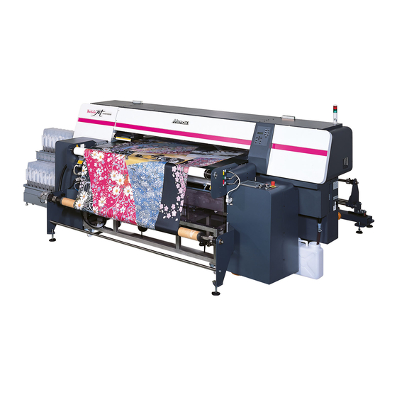
Foreword Thank you for purchasing MIMAKI "Tx400-1800B" color inkjet plotter. Tx400-1800B is a Color InkJet Printer for direct printing on fabric. This operation manual describes the operation and maintenance of model Tx400-1800B Color InkJet Printer. Read this manual carefully and make the most effective use of your printer. -
Page 9: For Safe Operation
For safe operation Pictorial signs Pictorial signs are used in this Operation Manual for safe operation of and in prevention of damages to the device. Pictorial signs and their meanings are given below. Read and fully understand before reading the text. Example of pictorial signs Indicates the case where it is assumed that misuse of the machine, ignoring this sign, as this may cause fire or poisoning. - Page 10 • When recoating adhesive, keep fire away and your distributor or a sales office of MIMAKI for be sure to turn OFF the belt heater and the main repair. Never repair your machine by yourself heater.
- Page 11 For safe operation Cautions and Requests CAUTION Use the drying heater • This is a printer performing the printing operation at a high speed. If you make the printing operation without using the drying heater, the wound-up fabric could be stained with color penetration to the back. Cautions about Installation CAUTION •...
-
Page 12: Position Of The Warning Label
For safe operation Position of the warning label This device is adhered with the warning label. Be sure to fully understand the warning given on the labels. In the case where any of the warning label has become so soiled that the warning message is illegible or has come off, purchase a new one from your local distributor or our office. -
Page 13: How To Read This Operation Manual
How to Read This Operation Manual... - Page 14 xiii...
- Page 15 Chapter 1 Before Use This chapter describes the items required to understand before use, such as the name of each part of the machine or the installation procedures. Installing the device ........1-2 Other setting ..........1-12 Where to install the device ......1-2 For waste ink tank ........1-12 Moving This Machine ........
-
Page 16: Installing The Device
Installing the device Where to install the device Secure sufficient space for installation before assembling this unit. Decide the place considering the size of the device and a space required for execution of printing. Machine Type Depth Height Total Weight 4300 mm 3500 mm 1650 mm... -
Page 17: Configuration And Function
Configuration and Function Front/Sides (11) (10) Name Function Take-up unit Unit to take up the printed fabric. Peeling roller Peels the fabric from the feeding belt. Fabric end guide Use when you wish to perform the peeling operation of the fabric more surely. Peeling sensor Monitors the position to peel the fabric. -
Page 18: Rear
Rear Name Function Feeding unit Unit to feed the roll media before printing. Centering motor Prevents meandering of the roll media with weaving. Roll holder Supports the paper core of two to three inches. Detects weaving of the media and changes its operation to the centering Cenntering sensor / operation. -
Page 19: Operation Panel
Configuration and Function Operation Panel Display Displaying state of the unit, setting items, errors, and so on. TEST DRAW key Press to start the test printing. DATA CLEAR key Press to erase received data. CLEANING key Press to start the head cleaning. USER TYPE key Press to change the user type. -
Page 20: Operation Touch Panel
Operation Touch Panel Each button is separated by color depending on its status and meaning. Yellow It means that the function is invalid or it is in the stand-by status. It means that the function is valid or it is in the operation status. Green It means that the buttons other than the RESET are in the error status. -
Page 21: Operation Panel (Front Surface Of Media Feeding System)
Configuration and Function Operation Panel (Front surface of media feeding system) Name Function When this button lights in red, the machine is in the warning status because of problem of some kind. To release the error status, first [RESET ALARM] button return the [Emergency] button (button 2) to the original status and then press this button. -
Page 22: Operation Panel (Rear Surface Of Media Feeding System)
Operation Panel (Rear surface of media feeding system) Name Function Adjusting dial Adjusts the pressure of the pressure roller. When you press “ I ”, the belt will move, and when you press “O”, it [BELT] button will stop. When you press “ I ”, the media will be fed, and when you press “O”, [FEEDING] button it will stop. -
Page 23: Ink Supply Unit
Configuration and Function Ink supply unit Name Function 2L Eco case Set a dedicated ink pack. Ink pack slot Set an eco case with the ink pack of each color. Ink IC slot Set an ink IC provided with the ink pack. Ink slot lamp Indicates the condition of the ink pack. -
Page 24: Carriage
Names and function of the parts under the front cover Under the front cover, there are the carriage, capping station, etc. necessary for printing operation. The mechanisms provided under the cover are explained below. Carriage The carriage is provided with print heads for plotting, etc. It is also provided with a head height adjustment screw for adjusting the head height according to the thickness of the fabric used. -
Page 25: Capping Station
Names and function of the parts under the front cover Capping Station The capping station consists of the ink caps, the wiper for cleaning the heads, etc. Ink cap : Prevent the nozzles in the ink heads from drying up. Wiper : Cleans the nozzles in the heads. -
Page 26: Other Setting
Other setting For waste ink tank The ink used for head cleaning and the like, a cleaning solution will be pooled in the waste ink tank. Insert the front edge of the waste ink hose into the waste ink tank. •... -
Page 27: Setup Of Media Feeding System
Other setting Setup of media feeding system You can set the following items in Setup. Pressing the [SETUP] button on the operation touch panel, perform the setting. • Setting of language to be displayed on the operation touch panel • Normal setting •... - Page 28 Normal setting For normal setting, you can set five items below: Tab Name Item Name Outline Sets the main heater temperature. This value is displayed in operation MAIN HEATER HEATER percentage. The main heater dehydrates the surface of the media right (default : 40%) after printing.
- Page 29 Other setting Select the item to be set and set it by pressing the [+]/[-]. • If you wish to cancel, press the [<]. Press the [+]/[-] of the item to be set. Press the [<] to return to the initial screen. 1-15...
-
Page 30: For Opening/Closing Cover
For opening/closing cover For opening/closing cover • Do not open the front cover and the maintenance cover L/R while the plotter is in operation. If you open the front cover or the maintenance cover L/R during plotting, the carriage will stop for safety, reselting in abortion of plotting. -
Page 31: For Power Cable
For power cable Connect the power cable with the following specification outlet: 10% Power voltage 50/60Hz 1Hz Frequency Capacity 36A and above • 100V system outlet cannot be used. • You cannot perform the installation of this machine. Request an electrician for doing the installation work. -
Page 32: Media
Fully understand the contents and use depending on the kind or the characteristic of fabric. • Use pre-processed fabric recommended by MIMAKI. • When setting the fabric, be sure to adjust the head height. Other wise, the fabric and/or the head can be damaged. - Page 33 Media Fabric conditions which enable to print Items Condition Remarks less than 5mm / one side edge Width variation Curve when expanded One-direction curve not allowed Slack height when expanded flat 2mm or less surface 15mm, Displacement roll Cloth (width of 500mm and less) is 2mm. edge Inner diameter of roll 2 ~ 3 inchs...
-
Page 34: For Ink
• Use textile pigment ink at a humidity of 40% to 60%. Precautions in handling the ink • Use Mimaki’s genuine ink. Troubles occurred from using other than Mimaki’s genuine ink shall be pay remedies even in the warranty period. -
Page 35: About Ink Supply Unit
For ink About ink supply unit The upper slot is called “numeric character side slot” and the lower slot is called “alphabetic character side slot”. Numeric character side ink pack slot Alphabetic character side ink Set the eco case with ink pack. slot lamp Displays status of the alphabetic character side ink pack. -
Page 36: Setting Ink
Setting ink Setting ink Prepare the 2L ink pack. • From the container box, take out the 2L ink pack and the ink 2L ink pack Ink IC Set the ink IC in the ink slot. • Insert the ink IC with the surface with metal upward. If you insert the wrong side by accident, it causes faulty or damage of the ink IC. -
Page 37: Changing An Ink Pack
Setting ink Attach the 2L eco case to the base. • For the ink pack and the ink IC in the same one container box, be sure to set in the same slot. If they are set in different slots, ink cannot be used in some cases. •... -
Page 38: Setting The Display Language
Setting the display language Set the language in which to display characters on the LCD. "English" has been set as the initial display language of the printer. Try to change the display language to "Japanese" here. Press the key in the local. F UNC T I ON S E TUP <... -
Page 39: Menu Mode
Menu Mode This machine has 4 modes. Each menu mode is described below. Media selection screen This is the mode in which the media has not been detected yet. The keys other than the key are effective. The display when the media is selected MED I A S E T Starts detecting the roll media Starts detecting the leaf media by... - Page 40 1-26...
- Page 41 Chapter 2 Basic Operations This chapter describes procedures and setting methods for ink and media preparation, and printing. User Type ............. 2-2 Attach the fabric winding roller ....2-18 Settings That Can Be Registered in Feed the media ..........2-20 Take up the media ........2-26 User Types ..........
-
Page 42: User Type
User Type Register a printing condition according to each of the media that you use in a user type beforehand. When you replace one media with another, you can set the optimum printing condition only by changing one user type to another. -
Page 43: Operation Flow
Operation Flow Turning the power ON Refer to P.2-4 “Turning the Power ON/OFF”. Setting media Refer to P.2-14 “Setting a Media”. Selecting a user type Refer to P.2-2 “Using the Registered User Types”. Test printing Refer to P.2-36 “Test Printing”. Printing Refer to P.2-38 “Printing Data”. -
Page 44: Turning The Power On/Off
Turning the Power ON/OFF Turning the Power ON Turn ON the power of the connected PC. Turn the power switch ON. • Move the power switch to the [ I ] side. Turn ON the power switch of the media feeding system side. - Page 45 Turning the Power ON/OFF Reset the alarm. • When you press the [ALARMS] (display in red) on the operation touch panel, alarm sections are displayed. • Press all alarm section buttons of 11 kinds to reset the alarm. (When it is reset, they are displayed in green.) •...
- Page 46 Reset the warning. • When you press the [ALARMS] (display in red) on the operation touch panel, warning sections are displayed. • Press all warning section buttons of 4 kinds to reset the warning. (When it is reset, they are displayed in green.) •...
-
Page 47: Turning The Power Off
Turning the Power ON/OFF Turning the Power OFF Check the following items when turning the power OFF. • If the machine is receiving data from the PC or if there is any data that has not been output yet • If the head has returned to the capping station •... -
Page 48: Automatic Function
Automatic function During automatic function, this machine receives the command directly from the inkjet printer. Each component of the feeding belt and this machine is controlled by the printer. As the feeding system has the centering unit, the media is set in the center as it is in the initial position. In addition, the media feeding during printing is controlled by the operation of the tension bar with two sensors. -
Page 49: Assistant Function
Assistant function Among the assistant devices prepared in this machine such as the centering unit, the belt heater, the belt washing unit, the external heater, etc., you can switch ON/OFF for some of them depending on the kind of media. Switch ON/OFF of the centering unit By using the centering unit, you can keep the media straight during printing. -
Page 50: Switch On/Off Of The Belt Washing Unit
Switch ON/OFF of the belt washing unit By using the belt washing unit, you can wipe off ink stuck through and on the feeding belt. Switch by pressing the [WASHING ON/OFF] on the operation touch panel. • If you wish to change to ON : lights in green •... -
Page 51: Switch On/Off Of The Belt Heater
Assistant function Switch ON/OFF of the belt heater By using the belt heater, you can keep the adherence and dryness of the feeding belt. Belt heater Switch by pressing the [BELT HEATER] on the operation touch panel. • If you wish to change to ON : lights in green •... -
Page 52: Switch On/Off Of The Main Heater
Switch ON/OFF of the main heater Switch by pressing the [HEATER ON/OFF] on the operation touch panel. • If you wish to change to ON : lights in green • For the main heater temperature setting, refer to “Normal setting” ( P.1-14). -
Page 53: Adjust The Angle Of The Main Heater
Assistant function Adjust the angle of the main heater When using the main heater, adjust the angle of the heater depending on the media angle to dehydrate the media normally after printing. • When using the main heater, make it parallel against the media surface from the free roller to the take-up device. -
Page 54: Setting A Media
Setting a Media Maximum Print Area The white area shown in the following figure represents the maximum print area. The area other than that is the dead space that cannot be printed. n the case of roll media : 1600mm In the case of leaf media : 230mm 10mm... -
Page 55: Outline Of Media Setting
Setting a Media Outline of media setting It is recommended to set media by two persons and more from the aspect of workability. • As the pressure roller is a heavy roll, much care should be taken for falling of the roller and being wedged during media setting. - Page 56 Adjusting weight of tension bar There is a wide variety of media including the difference in material such as natural fiber and synthetic fiber, or the difference in manufacturing method such as fabrics, knitted wear and others. Further, even with the same media, their stretching characteristics may vary due to differences in their pre-treatment process.
- Page 57 Setting a Media Method for attaching counter weight Remove the weight fixing screw. Weight fixing screw Insert the attached counter weight into the weight shaft of the floating tension bar. Counter weight • This machine provides one counter weight each for 2000g, 1300g, 600g, 300g and 100g.
-
Page 58: Attach The Fabric Winding Roller
Attach the fabric winding roller After washing belt, drops of water that could not be removed with the wiper of the washing unit may remain in some cases. If those drops are carried to the belt surface, it may stain the media before printing. You can remove drops adhering to the belt by attaching the fabric winding roller in advance. - Page 59 Setting a Media Attach the fabric winding roller with the fabric. • Attach the fabric winding roller by aligning it with the groove of the resin block around the feeding belt roller on the rear surface of this machine. Rotate the feeding belt to check that the fabric winding roller can rotate smoothly. 2-19...
-
Page 60: Feed The Media
Feed the media Press the [AUTOMATIC] on the operation touch panel to make the status to [MANUAL]. [FEEDING MANUAL] lever Operate the [FEEDING MANUAL] lever and the [FEEDING AUTOMATIC] lever on the rear control panel to select the rotation direction of the feeding unit. - Page 61 Setting a Media Set the media on the roll shaft. (1) Rotate the roll shaft and make the roll shaft slot turn Roll shaft slot Shaft fixing collar (2) Loosen the finger screw and move the shaft fixing collar. • Before moving the shaft fixing collar, be sure to check that the roll shaft slot turns up.
- Page 62 Centering unit sensor Put the media through the centering unit sensor and the dancing tension bar. • For the media of 1000mm and less in width, the media may exceed the adjustment range of the right and left movement of the centering sensor unit when you set the media on the center basis.
- Page 63 Setting a Media Check that the media is not set slanted from the media roll ends, the centering sensor, the tension bar and the pressure roller. • When you wish to set the media of maximum width (1860mm), set it on the position where it does not conflict with the belt encoder.
- Page 64 Adjust the position of the centering sensor. • Rotate the centering sensor unit to adjust the centering detection width. Maximum : Allows media misalignment of about 30mm. Minimum : Allows media misalignment of about 10mm. • Use it by adjusting the position between the maximum value and the minimum value at will. •...
- Page 65 Setting a Media Pressing the [WASHING OFF]/[MEDIA END OFF] as required, switch to the [WASHING ON]/ [MEDIA END ON]. Set the speed to about 10m/min by pressing the BELT SPEED [-]/[+]. When you press the [BELT OFF] to switch to the [BELT ON], the belt will operate and feed the media.
-
Page 66: Take Up The Media
Take up the media Take up the fed media on the empty paper core. Press the [AUTOMATIC] on the operation touch panel to make the status to [MANUAL]. Press PRESSURE ROLLER [UP] to change it to [DOWN]. Set the speed to about 10m/min by pressing the BELT SPEED [-]/[+]. - Page 67 Setting a Media Set the empty paper core on the take-up unit. • Set the empty paper core on the take-up unit in the same way as the setting of the roll shaft of the feeding unit. • The empty paper core with radial thickness of 5mm and more is recommended. •...
- Page 68 Adjust the fabric guide to slant the media end. • This machine checks the media position by detecting media with the peeling sensor. • The peeling sensor can detect the media when the media shades light emitting from the sensor. •...
- Page 69 Setting a Media Set the external heater. • When using the external heater, move it by adjusting the heater position so that heat can be applied evenly on the media front. • When using the external heater, the heat of the heater may be directly applied to the cover of the machine, the heater unit cable, etc.
-
Page 70: Set The Interleaving Paper Roll When Using Rc210 Ink
Set the interleaving paper roll when using Rc210 ink For using Rc210 ink, set the interleaving paper roll to prevent offset when the media is taken up. • Please use interleaving paper which the external diameter is 160mm or less at the maximum. •... - Page 71 Setting a Media Pull out the interleaving paper and fix the top edge of it on the paper core on which the media was pasted with tape. • Fix the interleaving paper with adhesive tape. Perform the work from the Step 7 in P.2-26 “Take up the media” and wind the media and the interleaving paper on the paper core.
-
Page 72: Adjusting The Head Height
Adjusting the Head Height Adjust the height of the head in line with the thickness of the fabric you use. • Unless the head is properly set at the height against the thickness of the fabric you use, deterioration of the printing quality or the breakage of the head could be caused. Perform the head height adjustment each time when you change the fabric. - Page 73 Setting a Media Move the carriage. • Move the carriage by hand until the head height adjusting rod comes on the media. • If the carriage hits the spacer or the fabric retainer, go to the step 9 and raise the head. Adjust the head height.
-
Page 74: Detecting The Media
Detecting the Media Media detection is a function for setting the printable area. Press on the media selection screen, and MED I A SE T ROL L < > L EA F select ROLL/LEAF. • If “LEAF” is selected, go to the step 5. Press the key. -
Page 75: When Changing The Origin
Setting a Media Set the width of the printing area. (1) Press to move the carriage to the left end of the printing area. • Put an arrow mark of the carriage on the setting position. (2) Press the key. •... -
Page 76: Test Printing
Test Printing Test printing is performed to check if printing failures (blurring and missing) due to nozzle clogging, etc. occur. Test Printing • When using a leaf media, set the media larger than the A3 size placed sideways • When using a roll media, check the media is not slacken. •... -
Page 77: Performing Head Cleaning
Test Printing Performing Head Cleaning Head cleaning can be performed in three ways. Select one according to the result of test printing. NORMAL : When any line is missing SOFT : When only head wiping is needed (when lines are bent) HARD : When poor image quality cannot be improved even by NORMAL or SOFT cleaning Press the... -
Page 78: Printing Data
Printing Data Starting a Printing Operation Setting a media. ( P.2-14) Select the user type (1 to 4). ( P.2-2) < L OCA L . * > [ # * * ] w i d t h : * * * * mm •... -
Page 79: Suspending Printing Operation
Printing Data Suspending printing operation Perform the following operation when stopping a printing operation halfway. Press the key during printing. < L OCA L . * > [ # * * ] w i d t h : 1 2 7 2 mm •... - Page 80 2-40...
- Page 81 Chapter 3 Extended Functions This chapter describes the operation procedures for using the machine more conveniently and each setting procedure. About User Types ......... 3-2 Setting Color pattern ........3-20 Registering All Printing Conditions Together Setting Drying Time ........3-21 (Type Registration) ........3-2 When moire fringes occur during printing ...3-22 How to Register User Types .......
-
Page 82: About User Types
About User Types Registering All Printing Conditions Together (Type Registration) This machine allows you to register printing conditions in each of the user types (1 to 4). Register a printing condition according to each media that you use in a user type beforehand. When you replace one media to another, you can set the optimum printing condition only by changing one user type to another. - Page 83 About User Types List of Functions to Be Set in User Types This section describes the overview of each function to be set and set values that can be registered in user types. The underlined has been set as default. Function Name Set Value Overview...
-
Page 84: Setting Media Correction
Setting Media Correction A pattern for media correction is printed and a media-feeding rate is corrected. After changing the type of the fabric, make correction of the feeding quantity of the media. If the correction value is not appropriate, stripes may appear on the printed image, thus resulting in a poor printing. - Page 85 Setting Media Correction Check the correction pattern and enter a correction T Y PE 1 A d j u s t value. • Press the to enter a correction value. Enter a correction value in "+":The boundary between the two bands is widened. Enter a correction value in "-":The boundary between the two bands is narrowed.
-
Page 86: Setting Media Feed
Setting Media Feed Setting feeding speed When feeding media slowly during printing, set the media feed. Press the key in LOCAL. F UNC T I ON S E TUP < EN T > Press the key. S E TUP S e l e c t Y P E 1 Press to select one of the types (1 to 4) and press the... -
Page 87: Setting Jog Speed
Setting Media Feed Setting jog speed Set the speed to move the media using the jog keys. Press the key in LOCAL. F UNC T I ON S E T UP < EN T > Press the key. S E T UP S e l e c t Y P E 1 Press... -
Page 88: Setting Belt Encoder
Setting belt encoder To improve the printing quality, you can use the function to monitor the feeding amount by the belt encoder. • When you make the belt encoder setting to “ON”, printing quality is improved, however the printing speed becomes slower than it is “OFF”. •... - Page 89 Setting Media Feed Press the key. B e l t J o i n t A d j . F : OF F R : OF F Press to set the Belt Joint B e l t J o i n t A d j .
-
Page 90: Setting Softness
Setting Media Feed Setting softness Even if you performed media adjustment ( P.3-6), if feeding unevenness cannot be solved, make the “softness” valid. • When you set the softness valid, the print quality with lower pass (6-pass and below) may be degraded in some cases. -
Page 91: Setting The Printing Quality
Setting the Printing Quality In the printing quality setting, the following items are set: Set Item Overview Set the direction for scanning and the number of pass. BI-D : Printing is performed in both outward and return directions of the carriage.Select this Scanning direction when you want to print in a shorter period of time. - Page 92 Setting the Printing Quality Press to select the drop size. T Y PE 1 : 6 0 0 x 4 5 0 D r o p S i z e M2 S 1 • Set Value : L3M2S1, L4M2S1, L5M3S1, L4M3S2, L5M4S3 •...
-
Page 93: Setting Priority Order
Setting Priority Order It is determined which is prioritized for printing, the setting by the machine (plot) or the setting by the PC (host). Set Value Overview Settings made in the computer (Host) are treated preferentially. HOST PLOT Settings made in this equipment (Plot) are treated preferentially. Items to be selected: Media Comp./ Print Mode / Ink Layers / Refresh / Use Head / Drying Time/Feed Speed Press the key in LOCAL. -
Page 94: Setting Automatic Cleaning
Setting Automatic Cleaning Setting of cleaning before printing You may make the setting so that the equipment automatically performs the cleaning of the head before starting the printing. The machine can perform a stable printing operation with its heads always kept clean. Set Item Overview Cleaning is performed before starting the printing. -
Page 95: Setting Of Cleaning While Printing
Setting Automatic Cleaning Setting of cleaning while printing It is set whether head cleaning is performed automatically during printing. In cleaning during printing, a cleaning interval is set according to the length of a printed media. Printing is interrupted each time a media is printed for the set length, and head cleaning is performed automatically during the interval. - Page 96 Press the key. T Y PE 1 C o l o r 2 3 4 1 6 7 8 Press to select the head to clean by block. T Y PE 1 C o l o r : 1 2 3 4 6 7 8 •...
-
Page 97: Setting Of Cleaning After Printing
Setting Automatic Cleaning Setting of cleaning after printing You can set cleaning so that it will be performed automatically after print operation is completed. If you leave the discharging defect that occurred during printing, ink or dust adhering to the nozzle surface, recovery will become more difficult with time. - Page 98 Press to select one of the cleaning type. T Y PE 1 T y p e o f t • Set Value : Normal / Soft / Hard Press the key. T Y PE 1 t i me m i n Pressing , select time up to starting cleaning T Y PE 1...
-
Page 99: Setting Of Power On Cleaning
Setting Automatic Cleaning Setting of Power ON cleaning Set whether you perform head cleaning automatically at turning ON the power supply or not. The type of cleaning differs depending on the power OFF time of the power supply. Set Value Overview Performs head cleaning at turning ON the power supply. -
Page 100: Setting Color Pattern
Setting Color pattern You may print the color pattern beside the image to be printed. Set Value Overview The color pattern to check the nozzle missing may be printed beside the images. Space:5 to 50mm Also, the space between the image and the color pattern. Press the key in LOCAL. -
Page 101: Setting Drying Time
Setting Drying Time The following items for ink drying time are set. Set Item Set Value Overview Ink drying time for each scanning is set. Each Line 0.0 to 10.0sec (During bidirectional printing, the machine stops for a certain period of time specified for each of the outward and return scanning.) Press the key in LOCAL. -
Page 102: When Moire Fringes Occur During Printing
When moire fringes occur during printing When moire fringes occur in the image during printing, terminate printing and perform the setting below. Set Value Overview Normally set this to OFF. Set these when there are moire fringes in the printed image. While watching the printed image, change the setting of MR1 to MR5. - Page 103 When moire fringes occur during printing • Even if you check with all setting values of MR1 to MR5, the moire fringes may remain. In such a case, select the setting value whose moire fringes have been most reduced among MR1 to MR5. In addition, by changing the resolution, the moire fringes may be reduced.
-
Page 104: Other Settings
Other Settings Change the settings according to the types of use. Press the key in LOCAL. F UNC T I ON S E TUP < EN T > Press the key. S E TUP S e l e c t Y P E 1 Press to select one of the types (1 to 4) and press the... -
Page 105: Machine Settings
Machine settings It is each type of setting for using this machine more comfortably. The following items are settable in MACHINE SETUP. Item Set value Outline If troubles such as the nozzle clogging is not solved, you can print with ALL, AB-, -BC Use Head A--, -B-, --C... -
Page 106: Switch Head To Use
Switch head to use If troubles such as the nozzle clogging is not solved, you can print with another head which has no error. Ex : When nozzle clogging in C line head is not solved Set to “AB-”. Set Value Overview A-- : Use the head of the A line. -
Page 107: Set Machine Name
Machine settings Set machine name The names of machines (machine No.) are set for recognizing them when they are connected to one another with a USB 2.0 interface used. Press the key in LOCAL. F UNC T I ON S E T UP <... -
Page 108: Set Stamp
Set stamp Set whether the current print condition (resolution / passes or others) is printed or not with an image data when printing data. Set Value Overview Prints the print condition with an image data. Prints only an image data. Press the key in LOCAL. -
Page 109: Performing Setting Related To Warning
Machine settings Performing setting related to warning Perform setting related to warning. The settable items are as below: Items Set Value Overview Set this to “OFF” when you wish to print continuously even if the warning informing you that the wiper cleaning time has come. Clean Wiper ON/OFF If this is set to “ON”, printing cannot be performed after the warning is... - Page 110 Set the time for replacing the mist fan filter/the time for recoating the adhesive on the belt Press the key in LOCAL. F UNC T I ON S E TUP < EN T > Press to select [MACHINE SETUP]. F UNC T I ON MACH I NE SE T UP <...
- Page 111 Machine settings Clear the used counter of the mist fan filter/the adhesive on the belt • If you clear the counter, the warning below becomes not displayed. ! M i s t F a n ! B e l t A d h e s i v e C l e a n F i l t e r R e a p p l y A d h e s i v e...
- Page 112 Perform setting of the warning related to nozzle recovery Press the key in LOCAL. F UNC T I ON S E TUP < EN T > Press to select [MACHINE SETUP]. F UNC T I ON MACH I NE SE T UP <...
-
Page 113: Setting Of Blank Data
Machine settings Setting of blank data Set the operation when there are blank data at the head of the data to be printed. Blank data Print data Set Value Overview Perform printing by feeding the blank part. Valid Invalid Perform printing by deleting the blank part. Press the key in LOCAL. -
Page 114: Setting Of Media Dryness Feed Using Main Heater
Setting of media dryness feed using MAIN heater The dryness feed is the function to dehydrate the part that was not dehydrated by the heater from the position where printing had been completed to the MAIN heater. When this function is “ON”, the machine performs feeding automatically to dehydrate media by the length set in advance after printing has been completed. - Page 115 Machine settings Press the key. D r y n e s s F e e d ワイハ゜ー レヘ゛ル S p e e d レヘ゛ル : AU TO / 1 0 Set the feeding speed by pressing D r y n e s s F e e d S p e e d 0 mm / s •...
-
Page 116: Printing The List Of Settings
Machine settings Printing the List of Settings You can print the setting contents and the information of this machine. Use this as a reference for the maintenance. Press the key in LOCAL. F UNC T I ON S E TUP <... -
Page 117: Confirming Machine Information
Confirming Machine Information The information of this machine can be confirmed. You may confirm the following items: Item Overview Version This displays the version information of the machine. Serial No. This displays serial number. Dealer No. This displays dealer number. Press the key in LOCAL. -
Page 118: Confirming Machine Condition
Confirming Machine Condition Confirm the machine condition such as error information or ink remaining. Press the key in LOCAL or REMOTE. I n k L e v e l 9 9 9 9 9 9 9 9 9 9 9 9 9 9 9 9 Press to select the information. -
Page 119: Maintenance
Chapter 4 Maintenance This chapter describes the items required to use this machine more comfortably, which are the methods for the daily care, the maintenance of the ink unit etc. Maintenance ..........4-2 If nozzle clogging is not solved (ink filling) ..4-24 Precautions for Maintenance ...... -
Page 120: Maintenance
Maintenance Maintain the machine regularly or as necessary so that its accuracy will be maintained and it can continue to be used for a long time. Precautions for Maintenance Pay attention to the following items when maintaining this machine. • Never disassemble the machine. Disassembling it can result in electric shock hazards or damage to the machine. -
Page 121: Maintaining The Capping Station
Maintaining the Capping Station Perform maintenance of the ink capand the wiper in the capping station (station maintenance). • If you use the machine with the ink cap or the wiper dirty, nozzle clogging may easily occur. Clean the ink cap and the wiper when the work is completed daily or when the roll media is replaced. Ink cap/wiper works respectively as follows: •... -
Page 122: Cleaning The Ink Cap
Cleaning the Ink cap Clean the cap when the failure of the picture image quality occurs, when the nozzle clogging is not solved even after performing cleaning function, or when it is not used for a long time. • If you use the machine with the ink cap dirty, nozzle clogging may easily occur. Clean the ink cap and the wiper when the work is completed daily or when the roll media is replaced. -
Page 123: Cleaning The Wiper
Maintaining the Capping Station Cleaning the Wiper Wiper has a function to wipe off ink etc. adhered on the nozzle of the head. Clean the wiper periodically to print in the good status. • If you use the machine with the wiper dirty, nozzle clogging may easily occur. Clean the ink cap and the wiper when the work is completed daily or when the roll media is replaced. -
Page 124: When The Message Of [Replace Wiper] Is Displayed
When the message of [Replace wiper] is displayed The wiper is consumable. When the right message is displayed, replace ! Wi p e r the wiper at once or remove the wiper rubber to rotate it to use the unused R e p l a c e Wi p e r edge. - Page 125 Maintaining the Capping Station Clean the guide ditch of the wiper. • Clean the guide ditch with a clean stick or cloth. • If dirt is hard to be removed, dip the clean stick in water etc. and then clean it. Wash the sponge under the wiper.
-
Page 126: Cleaning The Head Nozzles
Cleaning the Head Nozzles When nozzle missing occurs, clean the head nozzle. Is [NEAR END] or [INK END] displayed? Check the items • At the cleaning operation, perform ink absorbing. on the right At this time, if [NEAR END] or [INK END] is displayed, cleaning operation cannot be beforehand. - Page 127 Maintaining the Capping Station Fill up the cap with cleaning solution for maintenance, using a dropper. • Fill up the cap with cleaning solution on the verge of over- flow from the cap. • Fill the cleaning solution only to the head has nozzle miss- ing.
-
Page 128: Maintenance Of Head Nozzle Surface
Maintenance of head nozzle surface If you leave ink or dust adhering to the nozzle surface of the head during printing as it is, it may cause discharging defect or capping defect. Be sure to perform maintenance of the nozzle surface after the work is completed to keep the head nozzle surface clean. - Page 129 Maintaining the Capping Station About nozzle cleaning tool Use the nozzle cleaning tool when performing maintenance of the nozzle surface. When using the nozzle cleaning tool, check that there is no ink blot or dust etc. adhering to the tool. If ink blot or dust etc.
- Page 130 Perform maintenance of the head nozzle surface Press the key in LOCAL. S t a t i o n S e l a r r i a g e O u t Press to select [Nozzle Clean2]. S t a t i o n S e l o z z l e C l e a n 2 Press the...
- Page 131 Maintaining the Capping Station Open the maintenance cover R to clean the wiper. Clean the wiper cleaner. • Wipe off the ink sticking to the wiper cleaner with a clean stick dipped in cleaning solution for maintenance. • Be careful so that you may not get injured with the edge of the wiper cleaner.
- Page 132 Set the nozzle cleaning tool on the cap. (1) Wipe off ink or dust adhering to the nozzle cleaning tool with a waste cloth moisturized with maintenance cleaning liquid. • As the base rear surface of the nozzle cleaning tool touches the cap, especially make it has no dust.
- Page 133 Maintaining the Capping Station Moisturize the maintenance cloth set on the noz- zle cleaning tool with maintenance cleaning liq- uid. • Absorb maintenance cleaning liquid in a dropper and drop it on the maintenance cloth set on the nozzle cleaning tool. •...
- Page 134 Press the key. C a p C l e a n i n g C o mp l e t e d : e n t Clean the cap rubber. • Wipe off the ink sticking to the cap rubber with a clean stick dipped in cleaning solution for maintenance.
-
Page 135: Wash Ink Discharge Passage (Drain Wash)
Maintaining the Capping Station Wash ink discharge passage (Drain Wash) Wash the ink discharge passage regularly (about once a week) to prevent the head nozzles from clogging due to ink coagulation inside the passage. Press the key in LOCAL. S t a t i o n S e l a r r i a g e O u t Press... - Page 136 Press the key. P l e a s e Wa i t * * * * * * * * * - - - - - - - - - - - • After performing idle absorbing operation for 30 min., the machine returns to the media selection.
-
Page 137: When The Machine Is Not Used For A Long Time (Storage Wash)
Maintaining the Capping Station When the Machine Is Not Used for a Long Time (Storage Wash) When the machine is not going to be used for a week or more, use the cleaning function for custody to clean the head nozzles and ink discharge passage. After this, keep the machine in custody. Is [NEAR END] or [INK END] displayed? •... - Page 138 Maintaining the Capping Station Wash the sponge under the wiper. (1) Remove the sponge in the wiper frame and wash it with water. (2) Dry the sponge and put it into the wiper frame again. Press the key. F i l l U p Wa s h i n g s C o mp l e t e d : e n t...
-
Page 139: Cleaning The Ink Head And The Area Around It
Cleaning the Ink Head and the Area around It Because the ink head employs a very precise mechanism, due care needs to be taken when it is cleaned. Using a clean stick, etc., rub off gelatinous ink or dust that may stick to the lower part of the slider and the area around the ink head. -
Page 140: If The Positions Of Dots Shift
If the Positions of Dots Shift... If the width of the media to be used, the head height or the ink type is changed, correct the ink landing position during bidirectional printing (Bi) by the following operation to gain proper printing result. Example of a Printed Pattern Output The fourth in the + direction from the 0 position is... - Page 141 If the Positions of Dots Shift... Press the key to start pattern printing. * * P r i n t A d j * * P r i n t i n g • Multiple test patterns are printed. (The printed patterns are called Pattern 1, Pattern 2, Pattern 3 in the order of printing.) Press to move the correction pattern to the...
-
Page 142: If Nozzle Clogging Is Not Solved (Ink Filling)
If nozzle clogging is not solved (ink filling) Perform ink filling Even if you performed “Performing Head Cleaning”( P.2-37) or “Cleaning the Head Nozzles”( P.4-8) , nozzle clogging is not solved in some cases. If nozzle clogging is not improved, perform ink filling. There are three types of ink filling. - Page 143 If nozzle clogging is not solved (ink filling) Ink filling “Soft” Select [Ink Filling] of the maintenance menu. (1) Press the key. (2) Press to select [MAINTENANCE] and press the key. (3) Press to select [Ink Filling]. (4) Press the key.
- Page 144 Ink filling “Normal” Select [Ink Filling] of the maintenance menu. (1) Press the key. (2) Press to select [MAINTENANCE] and press the key. (3) Press to select [Ink Filling]. (4) Press the key. Press to select the head to I n k F i l l i n g C o l o r : 1 2...
- Page 145 If nozzle clogging is not solved (ink filling) Attach the ink port discharging jig. • Attach the ink port discharging jig on the Tx400. (1) Empty the waste ink bottle of the ink port discharging jig. (2) Paste the waste ink bottle on the position described in the right figure.
- Page 146 Insert the pipe adapter of the ink port discharging jig into the coupling valve of the ink port. Pipe adapter coupling valve Ink port • While taking out and putting in the pipe adapter, hold the joint of the ink port with your fingers.
- Page 147 If nozzle clogging is not solved (ink filling) Check the waste ink bottle. • When waste ink has been pooled in the bottle making up more than half of it, empty the bottle by following the procedures below. (1) Remove the ink port discharging jig. •...
- Page 148 Ink filling “Hard” Select [Ink Filling] of the maintenance menu. (1) Press the key. (2) Press to select [MAINTENANCE] and press the key. (3) Press to select [Ink Filling]. (4) Press the key. Press to select the head to I n k F i l l i n g C o l o r : 1 2...
- Page 149 If nozzle clogging is not solved (ink filling) Attach the ink port discharging jig. • Attach the ink port discharging jig on the Tx400. (1) Empty the waste ink bottle of the ink port discharging jig. (2) Paste the waste ink bottle on the position described in the right figure.
- Page 150 Insert the pipe adapter of the ink port discharging jig into the coupling valve of the ink port. Pipe adapter coupling valve Ink port • While taking out and putting in the pipe adapter, hold the joint of the ink port with your fingers.
- Page 151 If nozzle clogging is not solved (ink filling) Check the waste ink bottle. • When waste ink has been pooled in the bottle making up more than half of it, empty the bottle by following the procedures below. (1) Remove the ink port discharging jig. •...
- Page 152 Check ink filling status (filling check) Print a pattern to check if ink was properly filled with. Make the media feeding system printable. Switch each item below on the operation touch panel: • Press [MANUAL] to change it to [AUTOMATIC]. •...
- Page 153 If nozzle clogging is not solved (ink filling) Press the key several times to end the setting. color 8 color 1 4-35...
-
Page 154: Setting Regular Operations
Setting Regular Operations Various regular operations are performed with the power ON to prevent problems, such as ink coagulation, from occurring (Regular settings). For the regular settings, the following items can be set: Set Item Set Value Overview When a certain hour has passed, if you wish to perform the flushing 0hr 01min. -
Page 155: Set Cleaning Operation
Setting Regular Operations Set cleaning operation To prevent nozzle clogging, you can perform the cleaning operation periodically. Select [Routine Control] of the maintenance menu. (1) Press the key. (2) Press to select [MAINTENANCE] and press the key. (3) Press to select [Routine Control]. Press the key. -
Page 156: When Nozzles Missing Can Not Be Improved
When nozzles missing can not be improved NOZZLE RECOVERY: When nozzles missing can not be improved at specific points, other good nozzles can be used as alternatives for printing. You can set each item below for the nozzle recovery. Set Item Overview Regist. - Page 157 When nozzles missing can not be improved Press the key. * * N o z z l e R e c o v e r y * * P r i n t i n g • Printing starts. Nozzle pattern By pressing , feed the media.
- Page 158 Press the key. N o z z l e R e c o v e r y S e t L i n e A - 1 NG 1 : OF F • The next nozzle number registration screen is displayed. Perform the procedures in the Step 11 to 12 to register up to NG5.
-
Page 159: Set The Nozzle Recovery Function By The Line
When nozzles missing can not be improved Set the nozzle recovery function by the line You can set the nozzle recovery function by the line. Select [Nozzle Recovery] of the maintenance menu. (1) Press the key. (2) Press to select [MAINTENANCE] and press the key. -
Page 160: Check Valid/ Invalid Of The Nozzle Recovery Function
Check valid/ invalid of the nozzle recovery function You can check the set contents of the nozzle recovery function. Valid/ invalid of the nozzle recovery is displayed by the resolution on the screen. Select [Nozzle Recovery] of the maintenance menu. (1) Press the key. -
Page 161: Print The Setting List Of The Nozzle Recovery
When nozzles missing can not be improved Print the setting list of the nozzle recovery You can check the nozzle on which you set the nozzle recovery and the condition required for recovery. Select [Nozzle Recovery] of the maintenance menu. (1) Press the key. -
Page 162: When Waste Ink Tank Is Filled Up
When waste ink tank is filled up Ink used for the head cleaning etc. is pooled in the waste ink tank. When the waste ink tank is filled up, discard the waste ink in the waste ink tank. • When purchasing spare waste ink tank, contact nearest sales outlet or our sales office. •... -
Page 163: Cleaning Mist Fan Filter
Cleaning mist fan filter Clean the mist fan filter every day. Pull out the mist fan filter unit. Take the mist fan filter out. Clean the mist fan filter. • Wash the mist fan filter taken out and dry it. Bring the mist fan filter unit back to the original status. -
Page 164: If Negative Pressure Abnormality Occurs
If negative pressure abnormality occurs By the environment or aging, the pressure controlled in this machine may exceed the control range. The error display occurred by pressure abnormality falls into two types depending on the extent. Error Display Description Displays when the pressure is likely to exceed the controlled range. When the screen shown on the left is displayed, the pressure is in the ! P r e s s u r e A d j . - Page 165 If negative pressure abnormality occurs Rotate the adjustment screw of the throttle valve to A d j u s t T h r o t t l e V a l v e P r e s s u r e - 3 .
-
Page 166: Cleaning Of Peeling Sensor
Cleaning of peeling sensor To prevent the peeling sensor from the operation mistake due to blot, clean the peeling sensor periodically (about once a week). • The peeling sensor may be dirty because of ink mist generated at printing and steam generated when the fabric is evaporated. - Page 167 Chapter 5 Troubleshooting This chapter describes the corrective measures to be taken for a phenomenon suspected to be trou- ble and the procedures to clear the error number displayed on the LCD. Troubleshooting ................5-2 Image Quality Is Poor ..............5-3 If an error occurs in 2L ink pack or ink IC ........5-4 If printing is terminated due to media feeding system error .....5-6 Warning/Error Messages ...............5-11 Warning Messages ................5-11...
-
Page 168: Troubleshooting
Troubleshooting Take the appropriate actions as described below before taking the trouble as a failure. If the problem is still not solved after troubleshooting, contact your distributor or our service office. Failure phenomenon Cause Solution The power cable of the machine is not Securely connect the power cable of connected securely. -
Page 169: Image Quality Is Poor
Troubleshooting Image Quality Is Poor This section describes the corrective actions to be taken in case the image quality is not satisfactory. Take appropriate measures to remedy the problems with image quality. If the remedy does not work, contact your distributor or our service office. -
Page 170: If An Error Occurs In 2L Ink Pack Or Ink Ic
If an error occurs in 2L ink pack or ink IC If an error occurs in the 2L ink pack or the ink IC, a warning message is displayed. Printing, cleaning, and all the other operations that use ink become disabled if warning occurs. In this case, replace the ink pack immediately. - Page 171 Troubleshooting Messages and Solutions Message Cause Solution Contact our service office or the distributor in ! F i l l i n g Ink has not been filled up. your region. The ink of the ink pack has been ! I n k E n d completely used up.
-
Page 172: If Printing Is Terminated Due To Media Feeding System Error
If printing is terminated due to media feeding system error If a warning error occurs in the media feeding system during printing, a warning message is displayed. Check the status of the media feeding system, and then release the warning and restart printing. •... - Page 173 Troubleshooting Releasing method of warning when “!X Unit” is displayed When the warning of X-unit is displayed ! X U n i t P r e s s < F UNC > K e y Press on the Tx400 operation panel. ! X U n i t C h e c k : e n t...
- Page 174 Releasing method of warning when “!Media End” is displayed There are two methods to detect the media end: (1) Detection of media end by media end sensor (2) Detection of media end by change of tension bar When media end was detected by media end sensor When media end was detected by the media end sensor, [MEDIA END] on the operation touch panel lights in red and the buzzer sounds to inform you of the error.
- Page 175 Troubleshooting When media end was detected by change of tension bar When media end was detected by change of the tension bar, [TENSION BAR] on the operation touch panel lights in red and the buzzer sounds to inform you of the error. •...
- Page 176 Troubleshooting Select restart or termination of printing. • When you restart printing, press the key. < REMOT E . 1 > [ # 0 1 ] A L L / 8 PU / W3 2 1 / 0 . 0 m •...
-
Page 177: Warning/Error Messages
Warning/Error Messages If some trouble occurs, the buzzer sounds and the display shows a corresponding error message. Take appropriate measures to remedy the displayed error. • If there are multiple troubles, [ ! ] in the display will be inverted to E r r o r I n f o inform you of it. - Page 178 Message Cause Solution Contact our service office or the distributor in your ! Y M o t o r The time to replace the Y motor. region. R e p l a c e Y M o t o r The time to replace the mist fan ! M i s t F a n...
-
Page 179: Error Messages
Warning/Error Messages Error Messages When an error message is displayed, eliminate the error according to the chart below. If the same error message appears again, contact your distributor or our service office. Error messages Cause Solution An error occurred in the control E R R O R 0 1 ROM. - Page 180 Error messages Cause Solution error occurred E R R O R 2 0 Turn OFF the power to the machine and turn it ON communication between the I/ I / F B O A R D F board and the main PCB. again after a while.
- Page 181 Warning/Error Messages Error messages Cause Solution The reason may be one of the followings: • The positions of the left and the right ends of the media you set are not proper. • The position of the taking-up tension bar is not proper.
-
Page 182: About Alarm Display/Warning Display Of Media Feeding System
About alarm display/warning display of media feeding system Alarm list To access the alarm list, press the [Alarm] on the operation touch panel. If an alarm is detected, one or several alarms go forth and the corresponding item is changed to red. To release the error, first correct it in the corresponding unit, and then press the displayed alarm to return it to green. - Page 183 Warning/Error Messages Warning list To access the warning list, press the [Warnings] on the operation touch panel. If a warning is detected, one or several warnings go forth and the corresponding item is changed to red. To release the error, first correct it in the corresponding unit, and then press the displayed alarm to return it to green.
-
Page 184: When Power Of Adhesive Weakened
R e a p p l y A d h e s i v e • Mimaki’s genuine adhesive is solvent pressure sensitive adhesive. Be sure to wear the protection mask for organic solvent, the goggle and the gloves to recoat adhesive. -
Page 185: Be Sure To Check Before Recoating Adhesive
When power of adhesive weakened Be sure to check before recoating adhesive The power of adhesive on the feeding belt differs depending on the type/the used time of adhesive, media type/ thickness, temperature or humidity, etc. Depending on the adhesive type or other conditions, it is required to adjust the setting value of the pressure roller of the media feeding system. - Page 186 Set adhesive power You can change adhesive power by adjusting the pressure of the pressure roller. Adjust adhesive power to make the status of this machine as below: Rough standard for setting adhesive power (1) No lift shall be found on the media and the media edges within the carriage operating area at printing. (2) Media shall be fixed on the belt firmly until take-up starts at printing, and once take-up starts, the belt can be peeled off from the media smoothly.
-
Page 187: Peel Weakened Adhesive
When power of adhesive weakened Peel weakened adhesive To peel adhesive, the items below are required: • To peel adhesive coated on before shipment, use the remover attached to this machine. As adhesive is special one, you cannot peel it with kerosene nor diesel oil. Notes when removing adhesive •... - Page 188 Press the [AUTOMATIC] on the operation touch panel to make the status to [MANUAL]. Pressing the BELT SPEED [-]/[+], adjust it to 16 to 18m/min. First check that there is not the fabric or other object on the feeding belt, and then press the [BELT OFF] to operate the belt.
- Page 189 When power of adhesive weakened Pour remover on the belt so that it goes through the cloth. • Pour remover so that the drop does not drip off on the floor surface while the belt goes round once. If remover may adhere to other parts such as washing unit etc., it may adhere to adhesive again and cause the fixation fault.
- Page 190 After peeling off adhesive as much as possible with the resin board, remove the remaining adhesive on the belt surface with ethanol and the waste cloth. • After the work above is completed, recheck whether there is any adhesive left not being peeled or large dust.
-
Page 191: Coat New Adhesive
• Mimaki’s genuine adhesive is solvent pressure sensitive adhesive. Be sure to wear the protection mask for organic solvent, the goggle and the gloves to recoat adhesive. - Page 192 Paste adhesive tape (with smooth-surface) on the belt front surface. • Paste adhesive tape on the position as indicated in the figure (from both edges for right and left of the belt). Fabric feeding direction Belt upper surface Main body front side 10 ~ 20mm 25 ~ 30mm...
- Page 193 When power of adhesive weakened Press the [AUTOMATIC] on the operation touch panel to make the status to [MANUAL]. Pressing the BELT SPEED [-]/[+], adjust it to 10 to 12m/min. First check that there is not the fabric or other object on the feeding belt, and then press the [BELT OFF] to operate the belt.
- Page 194 Pour adhesive on the belt evenly in the width direction. • As adhesive is dehydrated and recoated little by little while the belt is moving round once, coat all over the belt by refilling adhesive on less part of it. •...
- Page 195 When power of adhesive weakened Switch to the [BELT OFF] to stop the belt. 5-29...
- Page 196 5-30...
- Page 197 Chapter 6 Appendix This chapter contains the lists of the specifications and functions of this machine. Main Body Specifications ..............6-2 Ink Specifications ................6-4 Inquiry Sheet ...................6-5 Function Flowchart ................6-6...
-
Page 198: Main Body Specifications
Main Body Specifications Item Tx400-1800B Method Drop-on-demand piezoelectric print heads Printing head Specification Twelve-heads (4 x 3 lines, Stagger arrangement) Resolution 300, 450, 600, 900, 1200 dpi 300 x 300 dpi : 2 / 4 / 8 pass, Unidirection / bidirection 300 x 450 dpi : 3 / 6 / 12 pass, Unidirection / bidirection... -
Page 199: Main Body Specifications
Variable between 1.3mm and 7mm from the lower face of the media Waste ink tank Bottle type 10 liters Interface USB 2.0 Command MRL-III (MIMAKI original command) During standby Less than 58 dB (FAST-A, back and forth and around.) Continuous Less than 65 dB operation noise... -
Page 200: Ink Specifications
Ink Specifications Item Form Dedicated ink pack Acidic dye ink Available at a later date Reaction dye ink Black /Cyan /Magenta /Yellow /Light cyan /Light magemta /Light brack /Blue/ Red/Orange Color Sublimation dye ink Black /Cyan /Magenta /Yellow /Light cyan /Light magemta /Blue/ Light blue Disperse dye ink Available at a later date Textile pigment ink... -
Page 201: Inquiry Sheet
Inquiry Sheet Use this sheet for troubles and abnormal functioning of the machine. Fill in the following necessary items and fax the sheet to our service office. Company name Person in charge Phone number Machine model Used OS Machine information Error messages Inquiry details *1. -
Page 202: Function Flowchart
Function Flowchart < L OC A L . 1 > [ # 0 1 ] w i d t h : * * * * mm O r i g i n S e t u p O r i g i n S e t u p X = 0 Y = * * * * * * * * * O r i g i n... - Page 203 Function Flowchart C l e a n i n g * * C l e a n i n g S t a r t : e n t 0 0 : 0 1 : 5 9 Me d i a H e a d H e i g h t I n k T y p e : R e a c...
- Page 204 < L OC A L . 1 > [ # 0 1 ] F UNC T I ON SETUP w i d t h : * * * * mm S E T U P < E N T > F UNC T I ON MAINTENANCE MA I N T E N A NC E...
- Page 205 Function Flowchart To P.6-10 To P.6-14 To P.6-20...
- Page 206 SETUP S E T U P T Y P E 1 T Y P E 1 S e l e c t : T Y P E 1 M e d i a C o mp . < E N T > S e t O r i g i n : e n t T Y P E 1...
- Page 207 Function Flowchart T Y P E 1 * * Me d i a C o m p T Y P E 1 P r i n t * * * * mm P r i n t i n g P a t t e r n C h e c k [ ] / [ ] T Y P E 1 A d j u s t...
- Page 208 From P.6-10 T Y P E 1 T Y P E 1 R e f r e s h < E N T > R e f r e s h : L e v e l 1 T Y P E 1 T Y P E 1 mm / i n c h <...
- Page 209 Function Flowchart T Y P E 1 B e f o r e P r i n t i n g : O n ON, OFF T Y P E 1 T Y P E 1 T Y P E 1 D u r i n g P r i n t i n g : O n C o l o r...
- Page 210 MAINTENANCE MA I N T E N A NC E S t a t i o n Carriage moves S t a t i o n < E N T > S e l : C a r r i a g e O u t S t a t i o n Carriage moves S e l...
- Page 211 Function Flowchart C a r r i a g e O u t To the media selection C o m p l e t e d : e n t Cleaning the Wiper To the media selection Replacing the Wiper To the media selection Fill the cleaning solution N o z z l e C l e a n i n g...
- Page 212 From P.6-14 MA I N T E N A NC E C a r r i a g e M a i n t Carriage moves C a r r i a g e < E N T > S e l : C a r r i a g e O u t MA I N T E N A NC E H e a d H e i g h t...
- Page 213 Function Flowchart To the media selection Clean around the head To the media selection End the printing P r i n t A d j u s t * * P r i n t A d j P r i n t A d j u s t P r i n t : e n t...
- Page 214 From P.6-16 MA I N T E N A NC E R o u t i n e C o n t r o l R o u t i n e C o n t r o l R o u t i n e C o n t r o l < E N T > F l u s h i n g <...
- Page 215 Function Flowchart R o u t i n e C o n t r o l I n t e r v a l = 0 h 0 m Hours : 0 to 24h Minutes : 0 to 59m : Change the setting value : Select the setting item R o u t i n e C o n t r o l I n t e r v a l...
- Page 216 MACHINE SET MA CH I N E S E T U P U s e H e a d U s e H e a d < E N T > H e a d L i n e : A L L ALL, AB-, -BC, A--, -B-, --C MA CH I N E S E T U P M a c h i n e N a m e...
- Page 217 Function Flowchart M i s t F a n S e t L i m i t : ON 0 to 30000m M i s t F a n R e s e t : e n t 6-21...
- Page 218 From P.6-20 From P.6-20 Wa r n i n g A d h e s i v e A d h e s i v e < E N T > C o u n t e r L i m i t <...
- Page 219 Function Flowchart A d h e s i v e S e t L i m i t : ON 0 to 30000m A d h e s i v e R e s e t : e n t D r y n e s s F e e d D r y n e s s F e e d S p e e d...
- Page 220 6-24...
- Page 221 D202080-14-29122011...
- Page 222 FW : 2.0 © MIMAKI ENGINEERING CO., LTD.2011...
Need help?
Do you have a question about the TEXTILE JET TX400 and is the answer not in the manual?
Questions and answers