Table of Contents
Advertisement
Quick Links
860463082
Issue 5, June 2014
www.commscope.com
SYSTIMAX 360
General
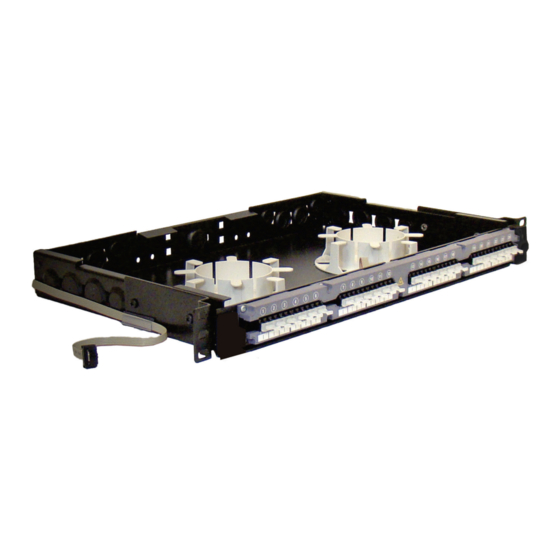
The SYSTIMAX 360™ iPatch
distribution shelf provides for connection of non-metallic Outside Plant (OSP) cable or Lightguide Building Cable
(LGBC) to 24 iPatch LC duplex fiber ports either by direct termination or splicing. Designed for use in an iPatch
system, this shelf is one unit high and can be mounted in a standard 19-inch rack with a universal hole pattern.
Both a sliding version and a fixed version are available.
Note: To use the SYSTIMAX 360 iPatch G2 shelf in an existing iPatch system, the iPatch Managers must be
running firmware version 8.1 or later, and the imVision
later. The System Manager firmware, used to manage the system, must be Version 7.1 or later. We recommend
that you upgrade the System Manager software to Version 7.1 or a later version before you install the shelf.
Ordering information is listed below:
Material ID
760193789
760193797
How to Contact Us
To find out more about CommScope
•
•
For technical assistance:
-
Within the United States, contact your local account representative or technical support at
1-800-344-0223. Outside the United States, contact your local account representative or
™
PartnerPRO
-
Within the United States, report any missing/damaged parts or any other issues to CommScope
Customer Claims at 1-866-539-2795 or email to claims@commscope.com. Outside the United
States, contact your local account representative or PartnerPRO Network Partner.
This product is covered by one or more of the following U.S. patents or their foreign equivalents:
6,285,293, 6,522,737, 5,923,807, 6,245,998 and 8,344,900.
™
iPatch
Instructions
®
G2 fiber shelf with faceplate is a SYSTIMAX
Part No.
360-iP-G2-1U-LC-FX
360-iP-G2-1U-LC-SD
SYSTIMAX 360™ iPatch
®
products, visit us on the web at
Network Partner.
© 2014 CommScope, Inc. All rights reserved
®
Fiber Shelf with Faceplate
®
Controller must be running firmware version 10.1 or
Description
®
iPatch
G2 LC fiber shelf, fixed
®
iPatch
G2 LC fiber shelf, sliding
®
G2 Fiber Shelf
http://www.commscope.com/
®
approved product. This
Page 1 of 13
Advertisement
Table of Contents

Related Manuals for CommScope SYSTIMAX 360 iPatch 360-iP-G2-1U-LC-FX


Summary of Contents for CommScope SYSTIMAX 360 iPatch 360-iP-G2-1U-LC-FX
- Page 1 ™ PartnerPRO Network Partner. Within the United States, report any missing/damaged parts or any other issues to CommScope Customer Claims at 1-866-539-2795 or email to claims@commscope.com. Outside the United States, contact your local account representative or PartnerPRO Network Partner. This product is covered by one or more of the following U.S. patents or their foreign equivalents: 6,285,293, 6,522,737, 5,923,807, 6,245,998 and 8,344,900.
-
Page 2: Specifications
860463082 www.commscope.com Instruction Sheet Specifications Fiber Optic Interface Industry-standard LC Compatible Fiber Size ® Multimode with 50 µm core diameter, such as LazrSPEED ® Multimode with 62.5 µm core diameter, such as OptiSPEED ® Singlemode with 8.3 µm core diameter, such as TeraSPEED... -
Page 3: Important Safety Cautions
860463082 Instruction Sheet Important Safety Cautions • To reduce the risk of fire, electric shock, and injury to persons, read, understand, and adhere to the following instructions as well as any warnings marked on the product. • Remote risk of electric shock. Never install the product in wet locations or during lightning storms. Never touch uninsulated communication wires or terminals. - Page 4 860463082 www.commscope.com Instruction Sheet Fiber type label Figure 1 Applying the Fiber Type Labels Step 2 – Routing the Panel Bus Jumper Follow the appropriate set of steps below to route the panel bus jumper in preparation for installing the shelf.
-
Page 5: Step 3 - Installing The Shelf
860463082 Instruction Sheet Step 3 – Installing the Shelf When installing multiple shelves in a rack, install the lowest shelf first and work toward the top of the rack. To install the shelf in the rack: 1. Mount the shelf in the rack using the four mounting screws provided (Figure 4). -
Page 6: Step 5 - Installing The Cable
860463082 www.commscope.com Instruction Sheet Step 4 – Installing the Patch Cord Trough To install the patch cord trough: 1. Position trough on shelf so that indentions behind captive screws rest on the standoffs as shown. 2. Using a Phillips head screwdriver, tighten the captive screw on each end of trough to secure it to shelf. - Page 7 860463082 Instruction Sheet Preparing the Cable for Splicing or Termination Whether you are splicing or terminating the fiber optic cable, perform the following steps: 1. Prepare the cable as shown in Figure 7. 2. Slide the liquid tight sealing nut and cable fitting onto the incoming fiber optic cable (Figure 8).
- Page 8 860463082 www.commscope.com Instruction Sheet Prepare the fiber optic cable for connection to the faceplate either by splicing or terminating the cable For instructions, see “Splicing and Installing the Cable” on page 9 or “Terminating and Installing the Cable” on page 11.
- Page 9 860463082 Instruction Sheet To splice and install the fiber optic cable: 1. On a clean work surface, prepare the incoming buffered fibers for splicing to the fiber pigtail by untangling them and laying them out flat. 2. Using the splicing materials appropriate for the type of splices you are making, splice the incoming buffered fibers to the pigtail.
- Page 10 860463082 www.commscope.com Instruction Sheet To install the splice trays in the RoloSplice: 1. Slide the splice tray over the rear latch and under the front latch in a RoloSplice pivoting tray. Orient the splice tray so that the indentation is centered under the front latch.
- Page 11 860463082 Instruction Sheet To terminate and install the fiber optic cable: 1. Install LC connectors on the buffered fibers. 2. Route the buffered fibers around the storage drums to the adapters on the back of the faceplate (Figure 12).
- Page 12 860463082 www.commscope.com Instruction Sheet Securing the Cable To secure the incoming fiber optic cable to the back of the shelf and rack: 1. Insert a cable tie retainer (provided) up through the hole in the cable support on the rear of the shelf on the side opposite from where the cable enters the shelf (Figure 13).
- Page 13 860463082 Instruction Sheet Step 6 – Installing the Cover and Door Install the plastic cover and trough door (both provided) to shield the shelf from foreign particles. The cover, which is made of clear, flame-retardant plastic, slides on and off the shelf. The door for the patch cord trough is hinged and has touch-latches for closing and opening.
Need help?
Do you have a question about the SYSTIMAX 360 iPatch 360-iP-G2-1U-LC-FX and is the answer not in the manual?
Questions and answers